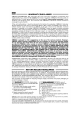
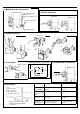
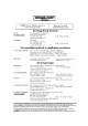
IMPORTANT STORING -40ºC INSTALLATION +80ºC Note: Pictures shown as block diagrams: not to scale or diagrammatically 1. Dimensions in mm 102 54 114 121 102 Bleed vent Exhaust vents 2.
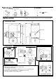
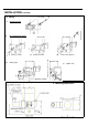
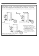
INSTALLATION (continued) 3. Fixing a Mounting Bracket b Pipe Mounting Kit (option) (i) (iv) Remove screws 2 screws (ii) Remove bracket clamp to pipe (iii) screw in new bracket (v) Tighten nuts Ø 50mm nominal 4.
. Make Pneumatic Connections 6. Remove Connector Soft sealing anaerobic hydraulic seal E.g. Loctite hydraulic seal 512 E.g. 6mm (1/4”) nylon pipe 1/4" NPT OR BSP 7. Expose Terminals c e f b d a 8. Insert Cable View Looking at Pins of Instrument 9.
11. Calibration When the instrument is first installed , or after a long period of downtime, a moderate zero shift is normal. This is due to the rubber diaphragms which are stretched by the internal springs. After a few operations, the instrument will settle into its normal operating condition. It is recommended that, under these circumstances, instruments should be exercised by alternately applying zero and full scale signals several times. Zero calibration should then be carried out. a. b.
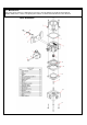
12. Maintenance Care must also be taken to re-align transfer passages correctly during reassembly of the instrument. Routine maintenance consists of replacing the restrictor screw if the internal orifice becomes blocked.
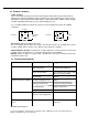
13. Product Variations 3 Wire Versions These are products designed for electrical control signals which differ from the normal 4-20. 060mA signals. An internal amplifier is fitted to translate the control signal into the required current through the coil. An external 12V-24V DC signal is required to power the amplifier, which should be capable of providing 25mA (low pressure) or 65mA.
M-1438/09/02