User’s Guide solartron 9 5 Shop online at 6 1 LDN-PS omega.com e-mail: info@omega.com For latest product manuals: omegamanual.
OMEGAnet ® On-Line Service www.omega.com Internet e-mail info@omega.com Servicing North America: USA: ISO 9001 Certified Canada: One Omega Drive, Box 4047 Stamford CT 06907-0047 Tel: (203) 359-1660 e-mail: info@omega.com Benelux: Postbus 8034, 1180 LA Amstelveen, The Netherlands Tel: +31 (0)20 3472121 FAX: +31 (0)20 6434643 Toll Free in Benelux: 0800 0993344 e-mail: sales@omegaeng.
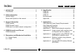
Index PSIM-AC 1 Introduction . . . . . . . . . . . . . . . . . . . . . . . . . . . . . .2 This Manual . . . . . . . . . . . . . . . . . . . . . . . . . . . . . . .2 PSIM-5V 6 Specification . . . . . . . . . . . . . . . . . . . . . . . . . . . . .12 PSIM-AC . . . . . . . . . . . . . . . . . . . . . . . . . . . . . . . . .12 PSIM-DC . . . . . . . . . . . . . . . . . . . . . . . . . . . . . . . .13 PSIM-5V . . . . . . . . . . . . . . . . . . . . . . . . . . . . . . . . .14 Environmental . . . . . . . . . .
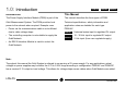
1.0: Introduction PSIM-AC PSIM-DC Introduction This Manual The Power Supply Interface Module (PSIM) is part of the The manual describes the three types of PSIM. Orbit Measurement System. The PSIM provides local Technical specifications, safety information and power to the network when required. Example uses: application notes are detailed for each type. • Power via the communications cable is not sufficient PSIM-AC due to cable voltage drops.
2.0: Safety Information PSIM-AC PSIM-DC PSIM-5V This equipment is designed as safety Class 1 apparatus CAUTION: Power Source. The PSIM-AC unit should to comply with EN61010-1. be connected to the mains supply via a suitable lead with a IEC320 socket. The user should fuse this Service Safety connection with a suitable fuse. Refer to Specification. This equipment has been designed and tested to meet Apply no more than 265V rms.
2.0: Safety Information (continued) PSIM-AC PSIM-DC PSIM-5V WARNING: Danger arising from loss of CAUTION ground. During a fault condition and upon loss This equipment contains no user serviceable parts. This of protective ground (earth), all accessible equipment must be returned to original supplier for all conducting parts - including controls that might service and repair. Dismantling the unit will invalidate the appear to be insulated - can render an electric warranty. shock.
3.
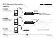
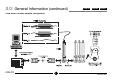
3.0: General Information (continued) PSIM-AC PSIM-DC PSIM-5V PSIM General Layout *Cable Lengths • PSIM-AC and PSIM-DC have a fixed 2m cable between PIE and power supply. ; 2m* PSIM-AC • PSIM-DC and PSIM-5V input cables are supplied 5m long. This may be cut to length as required.
3.
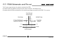
4.0: PSIM Schematic and Pin-out PSIM-AC PSIM-DC PSIM-5V The 5V power supply line from the network is isolated at the PSIM. All modules before the PSIM are powered from the network. Example: Orbit Network Card. All modules after the PSIM are powered from the external power supply connected via the PSIM. 0 V is common.
4.
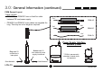
5.0: Dimensions and Mechanical Installation PSIM-AC PSIM-DC PSIM-5V 5.1 Power Supply The mounting plate must not be removed. The mounting plate is isolated and does not need to be at earth potential. The power supply may be mounted in any orientation. The power supply must not be exposed to fluids or excessive dust. Power supply cooling is by convection; allow room for air to flow around the unit.
5.0: Dimensions and Mechanical Installation PSIM-AC PSIM-DC PSIM-5V (continued) 5.2 PSIM T-CON is permanently attached, module does not separate. For more information on mounting, refer to the Orbit Measurement System Manual.
6.0: Specification PSIM-AC PSIM-DC PSIM-5V All specifications are for a PSIM supplying a full network of probes. PSIM-AC Input Voltage Current Connection Isolation Protection Recommended Line Fuse DC Output Output Voltage Output Current Output Regulation Transient Response Ripple and Noise Efficiency Protection see note 2 Thermal Derating LDN-PS 85 to 264 Vac @ 47 Hz to 440 Hz. 0.8 A via IEC320 connector 2500 Vac input/output Input fuse and filter (not user replaceable) 2A T (slo-blo) 250 V rating 5.
6.0: Specification (continued) PSIM-AC PSIM-DC PSIM-5V All specifications are for a PSIM supplying a full network of probes. PSIM-DC Input Line Voltage Current Connection Isolation Protection see note 3 DC Output Output Voltage Output Current Output Regulation Transient Response Ripple and Noise Efficiency Protection see note 2 Thermal Derating LDN-PS 10 to 30 Vdc. 1.1 A @ 12 Vdc; 0.5 A @ 24 Vdc (nominal).
6.0: Specification (continued) PSIM-AC PSIM-DC PSIM-5V PSIM-5V Line Voltage Input Current Connection Isolation Protection see note 1 see note 3 see note 2 5.1 Vdc Nominal as supplied by user 5.25 Vdc MAX 1.8 A MAX 5m flying lead (Red = positive, White = negative) None Current limiting resettable fuse Over voltage 112% to 132% of nominal Reverse connection Transient Note 1: No isolation or regulation is provided by the PSIM-5V.
6.
7.0: Applications PSIM-AC PSIM-DC PSIM-5V Orbit Network Power Supply Requirements Orbit Network Protection All Orbit Modules are designed to work from a supply Each PSIM provides a high level of protection for an voltage of 4.75V to 5.25 Vdc. When power is applied to Orbit Network. Protection for mis-connection, over a module its current consumption will cause a slight voltage and transients is provided. voltage drop across cables.
7.0: Applications (continued) PSIM-AC PSIM-DC PSIM-5V Voltage Drop Estimation The following information is for guidance only when planning an installation. Voltage measurements must still be made to ensure the right working voltage for each Orbit Module. Power Supply OUTPUT 9 5 PSIM-AC PSIM-DC see note 1 volt drop (from no load output) V = 5.3 x N (mV) 6 1 PSIM-5V Orbit Module with T-CON volt drop volt drop V = 2 x N x ( L+1 ) (mV) V = 0.04 x 1+2+3+...
7.0: Applications (continued) PSIM-AC PSIM-DC PSIM-5V Application 1: Basic Small Network Connection. • Power supplied to network from PC via network card, no PSIM used. • Modules connected using standard communication cables. Volt drop total in mV Then approximate voltage at end of network LDN-PS = = = = = = cable 1 + module (3 off) + cable 2 + module (3 off) (15.2 x 6) + 0.04(6+5+4+3+2+1) + (15.2 x 3) + 0.04(3+2+1) 138 mV nominal supply voltage - calculated volt drop 5.1 - 0.138 4.
7.0: Applications (continued) PSIM-AC PSIM-DC PSIM-5V Application 2: Large network with modules close to computer and at a distance. • Power supplied from PC and PSIM (located at a distance from PC). • Communications via standard communications cable and custom cable.
7.0: Applications (continued) PSIM-AC PSIM-DC PSIM-5V Volt drop V1 is calculated in a similar way to the previous example except there is only a single cable and 3 Orbit modules. The PSIM supplies power to remaining modules and are calculated separately. The long communications cable does not carry supply current and so has no affect on volt drops. Calculation for V1 volt drop = cable + module (3 off) = (15.2 x 3) + 0.
7.0: Applications (continued) PSIM-AC PSIM-DC PSIM-5V Application 3: Large Network using PSIM-5V and RS232IM for network control.
7.0: Applications (continued) PSIM-AC PSIM-DC PSIM-5V The PSIM-5V is powering the whole Orbit Network. PSIM-5V volt drop is calculated using 12 as the total number of Orbit modules; the RS232IM is included in this number. Total Voltage drop = PSIM-5V + modules (6 off) + Cable 1 + Modules (6 off) = (2 x 12 x [3+1]) + 0.04 (1+2+3+4+5+6+7+8+9+10+11+12)+ (15.2 x 6) + 0.04 (1+2+3+4+5+6) = 96 + 3.12 + 91.2 + 0.
7.0: Applications (continued) PSIM-AC PSIM-DC PSIM-5V Application 4: Modules located a long distance from computer. • Also for a computer that is not suitable for supplying power to Orbit Modules. • Power supplied from PSIM to modules. • Connection via long cable providing RS485, 0V reference and screening.
7.0: Applications (continued) PSIM-AC PSIM-DC PSIM-5V Application 5: Use with RS232 Interface Module (RS232IM). • Communication is via a RS232IM. • Power to the RS232IM and Orbit Modules is via PSIM.
WARRANTY/DISCLAIMER RETURN REQUESTS/INQUIRIES OMEGA ENGINEERING, INC. warrants this unit to be free of defects in materials and workmanship for a period of 13 months from date of purchase. OMEGA’s Warranty adds an additional one (1) month grace period to the normal one (1) year product warranty to cover handling and shipping time. This ensures that OMEGA’s customers receive maximum coverage on each product. Direct all warranty and repair requests/inquiries to the OMEGA Customer Service Department.
Where Do I Find Everything I Need for Process Measurement and Control? OMEGA…Of Course! Shop online at www.omega.