User’s Guide Shop online at omega.com e-mail: info@omega.com For latest product maunuals: omegamanual.
OMEGAnet ® Online Service www.omega.com Internet e-mail info@omega.com Servicing North America: USA: ISO 9001 Certified Canada: One Omega Drive, Box 4047 Stamford CT 06907-0047 Tel: (203) 359-1660 e-mail: info@omega.com 976 Bergar Laval (Quebec) H7L 5A1, Canada Tel: (514) 856-6928 e-mail: info@omega.
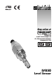
LV850 LEVEL SENSOR Please follow these installation, connection and adjustment instructions carefully. Failure to comply with these instructions or misuse of this equipment will void your warranty.
LV850 LEVEL SENSOR NOTES: ii
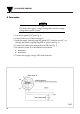
LV850 LEVEL SENSOR 1 Description Level Sensor LV850 is suitable for liquids with low relative dielectric constant εr (e.g. oil). Units come with Minimum and Maximum selector switch. It operates on the principle of electrical capacitance changes arising when an electrode surrounded by air is immersed in the medium. • LED status display • Selection of minimum and maximum function by changeover switch. Minimum switching Normally the sensor is immersed and the green LED indicates.
LV850 LEVEL SENSOR 2 Technical Data Temperature range short-time Ambient temperature Pressure resistance Response delay Degree of protection Input voltage Option: -20°C to +130 °C (-4°F to +266°F) to +150°C (+302°F) -20°C to +85°C (-4°F to +185°F) max. 25 bar (367.5 PSI) approx. 0.1 s IP 65 DC 9 ... 36 V - metal coupling for pipe extension (see fig.
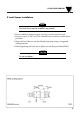
LV850 LEVEL SENSOR 3 Level Sensor Installation NOTE The Level Sensor may be installed in any attitude. 1. Ensure sufficient clearance space (see Fig. 1) in the container wall. • Ensure a type 3/4" NPT or G3/4A thread in the container wall has been provided. 2. Screw the Level Sensor into the threaded aperture using a recognized sealing material. 3. When tightening the level sensor please use the flats provided (SW32). CAUTION Do not overtighten.
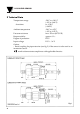
LV850 LEVEL SENSOR 4 Connection CAUTION Check that the supply voltage corresponds with the voltage rating shown on the system. 1. Loosen the gland (PG7)(see Fig. 1). 2. Unscrew the cover of the housing (C). 3. Feed the supply cable through the gland (PG7) and the cover (C), or through the metal coupling supplied as option (see Fig. 2). 4. Connect the cable to the terminal block (TB) (see Fig. 3). 5. Set selector switch (S) to minimum or maximum: 1. - minimum 2. - maximum 6. Connect the supply voltage.
LV850 LEVEL SENSOR 7. Increase the level until the Level Sensor is immersed in the medium. 8. Minimum Sensor: • Turn the potentiometer screw (E) to (-) until the LED (green) extinguishes. Then slowly turn to (+) until the LED indicates. Adjust the screw a further full turn to (+) to compensate for any tolerance. 9. Maximum Sensor: • Turn the potentiometer screw (E) to (+) until the LED (green) extinguishes. Then slowly turn to (-) until the LED indicates.
LV850 LEVEL SENSOR NOTES: 6
WARRANTY/DISCLAIMER OMEGA ENGINEERING, INC. warrants this unit to be free of defects in materials and workmanship for a period of 13 months from date of purchase. OMEGA’s Warranty adds an additional one (1) month grace period to the normal one (1) year product warranty to cover handling and shipping time. This ensures that OMEGA’s customers receive maximum coverage on each product. If the unit malfunctions, it must be returned to the factory for evaluation.
Where Do I Find Everything I Need for Process Measurement and Control? OMEGA…Of Course! Shop online at www.omega.