User’s Guide Shop online at www.omega.com e-mail: info@omega.
OMEGAnet ® Online Service www.omega.com Internet e-mail info@omega.com Servicing North America: USA: ISO 9001 Certified Canada: One Omega Drive, P.O. Box 4047 Stamford CT 06907-0047 TEL: (203) 359-1660 e-mail: info@omega.com 976 Bergar Laval (Quebec) H7L 5A1, Canada TEL: (514) 856-6928 e-mail: info@omega.
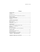
Manual No. M-3897 Content INTRODUCTION.......................................................................................................... 1 OVERVIEW........................................................................................................................1 W HAT ’S INCLUDED ........................................................................................................1 INDUSTRY STANDARD RELAY RACK CABLES AND OPTIONS.................................1 INSTALLATION...............
APPENDIX C - SILK-SCREEN.................................................................................15 APPENDIX D - COMPLIANCE NOTICES.............................................................16 FEDERAL COMMUNICATIONS COMMISSION STATEMENT ....................................16 EMC DIRECTIVE STATEMENT ...................................................................................16 FIGURES Figure 1- Operating Conditions ..........................................................................
Introduction and Installation Introduction Overview The OMG-USB-DIO48 provides six eight-bit ports that may be individually configured as inputs or outputs. What’s Included The OMG-USB-DIO48 is shipped with the following items. If any of these items is missing or damaged, contact the supplier.
Technical Technical Description The OMG-USB-DIO48 provides 48 channels of digital I/O configurable as inputs or outputs. Applications include PC based control and automation of sensors, switches, satellite antenna control systems, video and audio studio automation, security control systems, and other industrial automation. Software The OMG-USB-DIO48 ships with the SeaI/O suite of Windows 98/NT/ME/2000 drivers.
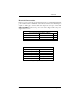
Technical Electrical Characteristics Figure 1, below provides the electrical characteristics of each Input/Output. Each port is buffered with a 74ABT245 octal bi-directional transceiver. Each input is capable of sinking up to 64 mA, while each output can source up to 32 mA. The OMG-USB-DIO48 requires a 5V power source and is shipped with a 5V power supply rated at 2.4 A. Recommended Operating Conditions Min Input 0V Source Sink Max 5.
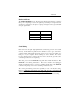
Technical Pull Ups Ten pin bussed resistor packs are installed to provide pull-ups to the input ports. These are installed on all ports. The pull-up resistor packs are rated at 10K ohms. Figure 2 below provides the bussed resistor and corresponding port. The resistors insure that no line is floating which is not connected. This provides consistent biasing on all un-terminated lines.
Technical Banks and Ports The OMG-USB-DIO48 has two 50 pin headers. Each 50 pin header is a bank of three ports, comprising a total of six eight bit ports. Each port is eight bits wide and may be configured as an input or output port. Figure 3 below gives the bank and port organization. Bank 1 – P2 Bank 2 – P3 Port A1 Port B1 Port C1 Port A2 Port B2 Port C2 Figure 3- Bank and Ports Serial String Each device has an eight digit alphanumeric serial string stored in non-volatile memory.
Technical 50 pin ribbon cable pin out Each of the two 50 pin ribbon cable headers has the following pin out as shown in Figure 4.
Programming Programming Application Programmers Interface (API) The SeaIO driver, API, and utilities have been included to provide control over the hardware in Windows environments. The following section is designed to help the customer understand the API connection to the actual I/O for the OMGUSB-DIO48. Complete documentation of the API can be found in the SeaI/O help file. Presetting an Output Port: Each port has an output register associated with it.
Programming Port Configuration: Each eight-bit port can be configured as inputs or outputs. The API provides a set adapter state call to access the control words. Note: The control panel also allows you to configure the device. Your program can over ride the control panel configuration when executed, but the control panel configuration will be the default on power up. The default settings are based on the settings in the control panel application when last changed and saved after re-booting.
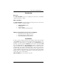
Programming Relative Addressing vs. Absolute Addressing The SeaIO API makes a distinction between “absolute” and “relative” addressing modes. In absolute addressing mode, the Port argument to the API function acts as a simple byte offset from the base I/O address of the device. For instance, Port #0 refers to the I/O address 0; Port #1 refers to the I/O address 1. Relative addressing mode refers to input and output ports in a logical fashion.
Programming Figure 7 below gives the absolute address for each bit on this device.
Programming Figures 8 and 9 are provided for the user to record their particular relative addressing setup, provided its constant. Print this page and fill in the tables starting in the top left corner of each and work from top to bottom, left to right. Start with zero (0) on the first input and increment by one on each additional input. Next move to outputs and again start with zero (0) and increment by one on each additional output.
Specifications Figure 9- Bit Relative Address (Print and fill in for your configuration) Specifications Environmental Specifications Specification Temperature Range Humidity Range Operating 0º to 50º C (32º to 122º F) 10 to 90% R.H. Non-Condensing Storage -20º to 70º C (-4º to 158º F) 10 to 90% R.H. Non-Condensing Power Consumption Supply line Rating +5 VDC 500 mA Mean Time Between Failures (MTBF) Greater than 150,000 hours.
Appendix A - Troubleshooting Appendix A - Troubleshooting Following these simple steps can eliminate most common problems. Install software first. After installing the software then proceed to adding the hardware. This places the required installation files in the correct locations. 1. Read this manual thoroughly before attempting to install the adapter in your system. 2. Use Device Manager under Windows to verify proper installation. 3.
Appendix B - How To Get Assistance Appendix B - How To Get Assistance Please refer to Troubleshooting Guide prior to calling Technical Support. 1. Begin by reading through the Trouble Shooting Guide in Appendix A. If assistance is still needed please see below. 2. When calling for technical assistance, please have your user manual and current adapter settings. If possible, please have the adapter installed in a computer ready to run diagnostics. 3.
Appendix C - Silk-Screen Appendix C - Silk-Screen OMG-USB-DIO48 Page 15
Appendix D - Compliance Notices Appendix D - Compliance Notices Federal Communications Commission Stateme nt FCC - This equipment has been tested and found to comply with the limits for Class A digital device, pursuant to Part 15 of the FCC Rules. These limits are designed to provide reasonable protection against harmful interference when the equipment is operated in a commercial environment.
WARRANTY/DISCLAIMER OMEGA ENGINEERING, INC. warrants this unit to be free of defects in materials and workmanship for a period of 13 months from date of purchase. OMEGA’s WARRANTY adds an additional one (1) month grace period to the normal one (1) year product warranty to cover handling and shipping time. This ensures that OMEGA’s customers receive maximum coverage on each product. If the unit malfunctions, it must be returned to the factory for evaluation.
Where Do I Find Everything I Need for Process Measurement and Control? OMEGA…Of Course! Shop online at www.omega.