
- OMEGA Engineering, Inc. Power Supply Product Manual


11.. . APPENDIX A: MASTER ICON FILE REFERENCE
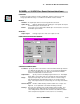
USING THE OMP-MODL11-14
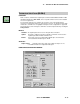
Port (1 to 6) and Channel (A to H) where the actual Interface Module
channel is installed will be used for the name.
Output Name: Specify a name for the Output signal from this icon. This Output
Name will be referenced by other icons downstream in the Program Net.
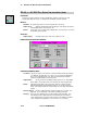
Input Type: Specifies the wiring configuration to be used.
2-Wire is typically used for measurements of higher resistance values or
with short lead wire runs where the resistance of the lead wires induces
negligible error. With 2-wire configuration, all four input channels can be
used.
3 and 4-Wire configurations are used where the lead wires to the element
are longer and/or premium measurement accuracy is required. Both 3 and
4-wire configurations compensate for the lead wire resistance. 3-wire
provides nearly the same performance as 4-wire using only 3 wires instead
of 4.
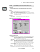
If 3 or 4-wire configuration is selected, the input requires two input
channels. From within the A and C channel icons, selecting 3 or 4-wire will
result in a displayed message that a second channel will be deleted (B or
D).
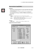
Range: Specify the input range to be used for this channel. For optimum resolution,
choose the narrowest range that will meet the signal fluctuation without
exceeding the Full Scale Range. If the input exceeds the selected range, an
over-range value will be logged.
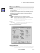
Input Res: Specify the RTD 0’C resistance value. Both 100 and 1000 ohm devices are
supported.
Curve (alpha): Specify the alpha coefficient for your type of RTD. This coefficient
is used in the conversion equation of resistance to temperature. If
unknown, contact the RTD supplier for input. European (most common) =
0.00385 and American = 0.00392.
Units: Select Degrees C or F
Filtering: First order noise filtering can be enabled during channel reading. First
order filtering reduces high frequency noise that may be picked up by
sensor wiring with the cost that it slows down the rate at which a channel
can be sampled. See the OMP-MODL User’s Manual Appendix for
discussion on use of filtering.
AC Noise Reject: Enables software filtering of 50Hz or 60Hz noise on inputs. See
the OMP-MODL User’s Manual Appendix for an explanation of the 50/60 Hz
filtering technique.
Change: Click on CHANGE to switch the icon / dialog box between thermistor,
resistance, or RTD type input.