User’s Guide Shop online at omega.com e-mail: info@omega.com For latest product manuals: omegamanual.
OMEGAnet® Online Service omega.com Internet e-mail info@omega.com Servicing North America: U.S.A.: ISO 9001 Certified Canada: One Omega Drive, P.O. Box 4047 Stamford, CT 06907-0047 TEL: (203) 359-1660 e-mail: info@omega.com 976 Bergar Laval (Quebec) H7L 5A1, Canada TEL: (514) 856-6928 e-mail: info@omega.ca FAX: (203) 359-7700 FAX: (514) 856-6886 For immediate technical or application assistance: U.S.A.
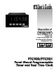
z 6-DIGIT 0.56" RED SUNLIGHT READABLE DISPLAY z 4 SEPARATE DISPLAYS (Timer, Counter, Real-Time Clock, and Date) C U L R z CYCLE COUNTING CAPABILITY US LISTED IND. CONT. EQ.
TABLE OF CONTENTS General Meter Specifications. . . . . . . . . Optional Plug-In Cards and Accessories Installing the Meter . . . . . . . . . . . . . . . . Setting the Jumpers . . . . . . . . . . . . . . . Installing Plug-In Cards . . . . . . . . . . . . . . . . . . . . . . . . . . . . . . . . . 4 5 6 6 7 Wiring the Meter . . . . . . . . . . . . . . . . . . . . . . 7 Reviewing the Front Buttons and Display . . 10 Programming the Meter. . . . . . . . . . . . . . . . 11 Factory Service Operations . . .
OPTIONAL PLUG-IN CARDS AND ACCESSORIES SETPOINT CARDS (LDP6-CDS) WARNING: Disconnect all power to the unit before installing Plug-in cards. The PTC900/PTC/901 series has 4 available setpoint alarm output plug-in cards. Only one of these cards can be installed at a time. (Logic state of the outputs can be reversed in the programming.
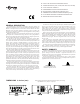
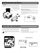
1.0 INSTALLING THE METER Installation The meter meets NEMA 4X/IP65 requirements for indoor use when properly installed. The meter is intended to be mounted into an enclosed panel. Prepare the panel cutout to the dimensions shown. Remove the panel latch from the meter. Slide the panel gasket over the rear of the meter to the back of the bezel. The meter should be installed fully assembled. Insert the meter into the panel cutout.
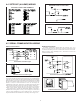
3.0 INSTALLING PLUG-IN CARDS To Install: The Plug-in cards are separately purchased optional cards that perform specific functions. These cards plug into the main circuit board of the meter. The Plug-in cards have many unique functions when used with the meters. CAUTION: The Plug-in card and main circuit board contain static sensitive components. Before handling the cards, discharge static charges from your body by touching a grounded bare metal object.
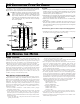
4.1 POWER WIRING AC Power DC Power Terminal 1: VAC Terminal 2: VAC Terminal 1: +VDC Terminal 2: -VDC 4.2 TIMER INPUT WIRING Before connecting the wires, the Timer Input logic jumper should be verified for proper position.
4.4 SETPOINT (ALARMS) WIRING SOURCING OUTPUT LOGIC CARD SETPOINT PLUG-IN CARD TERMINALS SINKING OUTPUT LOGIC CARD 4.5 SERIAL COMMUNICATION WIRING RS232 Communications RS485 Communications The RS485 communication standard allows the connection of up to 32 devices on a single pair of wires, distances up to 4,000 ft. and data rates as high as 10M baud. The same pair of wires is used to both transmit and receive data.
4.6 REAL-TIME CLOCK WIRING (PTC901) Time synchronization between multiple PTC901 meters can be accomplished through a hardware interface on the Real-Time Clock option card. This RS485 type interface allows connection of up to 32 PTC901 meters in a two-wire multidrop network, at distances up to 4000 ft. In a synchronization network, one PTC901 meter is programmed as the Host, while all other meters are programmed as Slaves.
6.0 PROGRAMMING THE METER OVERVIEW PROGRAMMING MENU DISPLAY MODE The meter normally operates in the Display Mode. In this mode, the meter displays can be viewed consecutively by pressing the DSP key. The annunciators to the left of the display indicate which display is currently shown; Timer (TMR), Cycle Counter (CNT), or Date (DAT). The Time Display for the Real-Time Clock is shown with no annunciator. Any of these displays can be locked from view through programming. (See Module 3.
6.1 MODULE 1 - TIMER INPUT PARAMETERS ( ) PARAMETER MENU Module 1 is the programming module for the Timer Input Parameters. In the Display Mode, the TMR annunciator indicates the Timer display is currently being shown. An EXCHANGE PARAMETER LISTS feature, which includes the Timer Start and Timer Stop Values, is explained in Module 2.
FLASH TIMER ANNUNCIATOR TIMER RESET AT POWER-UP « « ª ª The Timer can be programmed to Reset at each meter power-up. This parameter allows the Timer annunciator (TMR) to flash when the Timer is running or stopped/inhibited. Select if a flashing indicator is not desired. TIMER INPUT STATE AT POWER-UP « ª Determines the “Run/Stop” State of the Timer at Power-up. This parameter does not apply to timer input operation.
DISPLAY SELECT (Level Active) DISPLAY HOLD (Level Active) « « « ª ª When active (maintained action), the meter continuously scrolls through all displays that are not “locked-out” in the Display mode. (See Module 3 for Display Lock-out details.) A sub-menu provides Scrolling Speed selection. When active (maintained action), the meter “freezes” the display values entered as in the sublist, while normal meter operation continues internally. Program only one user input for this function.
CHANGE DISPLAY INTENSITY LEVEL « OUTPUT SET (Level Active) « ª « « ª ª ª When activated (maintained action), the meter continually activates the output for all Setpoints entered as in the sublist. When activated (momentary action), the display intensity changes to the next intensity level (of 4). The four levels correspond to Display Intensity Level ( ) settings of 0, 3, 8 & 15.
6.3 MODULE 3 - DISPLAY AND PROGRAM PARAMETERS LOCK-OUT ( ) PARAMETER MENU ** These parameters only appear if a Setpoint option card is installed. = Setpoint Number 1 thru 4 Module 3 is the programming module for setting the Display Lock-out Parameters and the “Quick Programming Mode” Value Access Parameters. In the Quick Programming mode, after the PROGRAM LOCKOUT PARAMETERS and before the Security Code ( ), a Display Intensity Level ( ) parameter is available when the security code is non-zero.
6.4 MODULE 4 - CYCLE COUNTER PARAMETERS ( ) PARAMETER MENU Module 4 is the programming module for the Cycle Counter Parameters. In the Display Mode, the CNT annunciator indicates the Cycle Counter display is currently being shown. An EXCHANGE PARAMETER LISTS feature, which includes the Cycle Counter Start and Stop Values, is explained in Module 2. CYCLE COUNTER START VALUE « ª CYCLE COUNTER COUNT SOURCE to 999 The Cycle Counter returns to this value whenever a Cycle Counter Reset occurs.
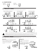
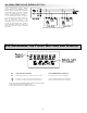
Timing Diagrams for Predefined Timer Operating Modes NOTE: Input A is shown as a Sourcing input (active high). If a Sinking input (active low) is used, the logic levels for Input A would be inverted. On-Delay / Interval Timing On-Delay Timing Input A Input A T Output 1 T T1 Output 1 Off-Delay Timing T2 T Interval Timing (Level triggered) Input A Input A T T Output 1 T T Output 1 The input signal must be wired to both the Input A and User Input 1 terminals.
6.6 MODULE 6 - SETPOINT (ALARM) PARAMETERS ( ) This module can only be accessed if a Setpoint Card is installed. PARAMETER MENU = Setpoint Number 1 thru 4 Module 6 is the programming module for the Setpoint (Alarm) Output Parameters. This programming module can only be accessed if a Setpoint card is installed. Depending on the card installed, there will be two or four Setpoint outputs available.
TIME-OUT VALUE « TIMER STOP « to ª ª The Time-Out Value only appears when the Setpoint Action ( ) is programmed for Timed Output mode ( ). In this mode, the Time-Out Value is the Setpoint Output time duration, from activation to deactivation. This value is always entered in minutes, seconds, and hundredths of seconds format. The maximum Time-Out Value is 99 minutes 59.99 seconds.
6.7 MODULE 7 - SERIAL COMMUNICATIONS PARAMETERS ( ) This module can only be accessed if a Serial Communications Card is installed. PARAMETER MENU * Only appears if the Real-Time Clock Card is installed. Module 7 is the programming module for the Serial Communications Parameters. These parameters are used to match the serial settings of the meter with those of the host computer or other serial device, such as a terminal or printer.
SENDING SERIAL COMMANDS AND DATA Command String Examples: When sending commands to the meter, a string containing at least one command character must be constructed. A command string consists of a command character, a value identifier, numerical data (if writing data to the meter) followed by the command terminator character * or $. 1. Address = 17, Write 350 to Setpoint 1 String: N17VE350$ 2. Address = 5, Cycle Counter value, response time of 50 to 100 msec. min.
Abbreviated Transmission ( = ) BYTE DESCRIPTION 1-12 13 14 15 16 17 12 byte data field, 6 bytes for number, up to 3 bytes for decimal points. (Carriage return) (Line feed) Auto/Manual Mode Register (MMR) ID: U This register sets the controlling mode for the outputs. In Auto Mode (0) the meter controls the setpoint output. In Manual Mode (1) the outputs are defined by the registers SOR.
COMMUNICATION FORMAT Data is transferred from the meter through a serial communication channel. In serial communications, the voltage is switched between a high and low level at a predetermined rate (baud rate) using ASCII encoding. The receiving device reads the voltage levels at the same intervals and then translates the switched levels back to a character. The voltage level conventions depend on the interface standard. The table lists the voltage levels for each standard.
TIME DISPLAY FORMAT « ª 12-59p 12-59 To calibrate the RTC, install the meter in its normal operating environment, and set the time based on a known accurate reference (such as the WWV broadcast or the Atomic Clock reference which is available via the internet). After 30 days of normal operation, compare the RTC time to the reference, and note the amount of time gained or lost. Refer to the tables on the next page for the proper Offset value to enter, given the amount of time drift observed.
6.9 MODULE 9 - FACTORY SERVICE OPERATIONS ( ) PARAMETER MENU DISPLAY INTENSITY LEVEL E -&7 « ª RESTORE FACTORY DEFAULTS Enter the desired Display Intensity Level (0-15) by using the arrow keys. The display will actively dim or brighten as the levels are changed. This parameter also appears in Quick Programming Mode when enabled. Use the RST and/or arrow keys to display and press PAR. The meter will display and then returns to . Press DSP key to return to the Display Mode.
PARAMETER VALUE CHART Programmer ________________ Date ________ Clock Timer Meter# _____________ Security Code __________ 3-LOC Display and Program Lock-out Parameters 1-INP Timer Input Parameters DISPLAY rANGE INP OP FILtEr t dir t Strt PARAMETER TIMER RANGE TIMER INPUT OPERATION FACTORY SETTING DISPLAY USER SETTING t-dSP C-dSP rtC-d rtC-t Sp-1 SP0F-1 tOUt-1 Sp-2 Sp0f-2 tOUt-2 sp-3 sp0f-3 tOUt-3 sp-4 sp0f-4 tOUt-4 t Strt t StOP C Strt C StOP SEt-t COdE SSSSSS LEVEL TIMER INPUT FILTERING TIMING DI
6-SPt Setpoint (Alarm) Parameters DISPLAY ASM-n ACt-n OUt-n ON-n PARAMETER USER SETTING NONE LAtCH NOr VALUE VALUE 000000 000000 VALUE VALUE 000100 000100 DAILY ON OCCURRENCE (A) Mon-Fri Mon-Fri Mon-Fri Mon-Fri DAILY ON OCCURRENCE (B)* Mon-Fri Mon-Fri Mon-Fri Mon-Fri DAILY OFF OCCURRENCE (A) Mon-Fri Mon-Fri Mon-Fri Mon-Fri DAILY OFF OCCURRENCE (B)* Mon-Fri Mon-Fri Mon-Fri Mon-Fri NO NO NO NOr NO NO NO NOr NO NO NO NOr NO NO NO NOr OUTPUT LOGIC SETPOINT ON (A) SETPOINT ON VALUE
PAR PAR PAR PAR PAR PAR PAR PAR PAR F1/F2 Keys Display Intensity Level Set Time Baud Rate Setpoint Select Predefined Timer Operating Mode Cycle Counter Count Source Timer Display Lock-out Timer Range Factory Service Code Set Date Data Bit Set Day Parity Bit Setpoint Action Time Display Format Date Display Format Time-out Value Auto Change for Daylight Savings Time Real-Time Clock Print Formatting Calibrate Real-Time Clock Daily On Occurrence Timer Start Value Access Timer
PART NUMBER INFORMATION DESCRIPTION PART NUMBERS Timer, 85-250 VAC power PTC900 Timer, 11-36 VDC/24 VAC power PTC900-LV Timer, 85-250 VAC power, green LED display PTC900-GN Timer, 11-36 VDC/24 VAC power, green LED display PTC900-GN-LV Real-Time Clock, 85-250 VAC power PTC901 Real-Time Clock, 11-36 VDC/24 VAC power PTC901-LV Real-Time Clock, 85-250 VAC power, green LED display PTC901-GN Real-Time Clock, 11-36 VDC/24 VAC power, green LED display PTC901-GN-LV ACCESSORIES DESCRIPTION PART NUM
WARRANTY/DISCLAIMER OMEGA ENGINEERING, INC. warrants this unit to be free of defects in materials and workmanship for a period of 25 months from date of purchase. OMEGA’s WARRANTY adds an additional one (1) month grace period to the normal two (2) year product warranty to cover handling and shipping time. This ensures that OMEGA’s customers receive maximum coverage on each product. If the unit malfunctions, it must be returned to the factory for evaluation.
Where Do I Find Everything I Need for Process Measurement and Control? OMEGA…Of Course! Shop online at omega.