
- Omega Real-Time Clock Users' Guide

8
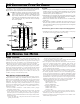
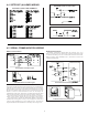
Before connecting the wires, the Timer Input logic jumper should be verified for proper position.
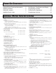
4.2 TIMER INPUT WIRING
CAUTION: Timer Input common is NOT isolated from User Input common. In order to preserve the safety of the meter application, the timer input
common must be suitably isolated from hazardous live earth referenced voltage; or input common must be at protective earth ground potential. If not,
hazardous voltage may be present at the User Inputs and User Input Common terminals. Appropriate considerations must then be given to the potential
of the User Input Common with respect to earth ground; and the common of the isolated plug-in cards with respect to input common.
Two Wire Proximity, Current Source Current Sourcing Output
Interfacing With TTL
Current Sinking Output
Switch or Isolated Transistor; Current Sink
Switch or Isolated Transistor; Current Source
Emitter Follower; Current Source
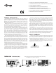
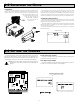
4.1 POWER WIRING
AC Power
Terminal 1: VAC
Terminal 2: VAC
DC Power
Terminal 1: +VDC
Terminal 2: -VDC
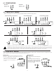
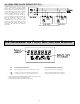
4.3 USER INPUT WIRING
Before connecting the wires, the Timer Input logic jumper should be verified for proper position. When the user input is configured for cycle
count, in module 4, the count input should be wired between terminals 7 & 10.
Sourcing Logic
Terminals 7-9:
+ VDC through external switching device
Terminal 10:
-VDC through external switching device
The user inputs of the meter are internally
pulled down to 0 V with 22 KΩ resistance.
The input is active when a voltage greater
than 3.6 VDC is applied.
Sinking Logic
Terminals 7-9
Terminal 10
The user inputs of the meter are internally
pulled up to +12 V with 22 KΩ resistance.
The input is active when it is pulled low
(<0 .9 V).
Connect external switching device between the
appropriate User Input terminal and User Comm.
}