
- Omega Real-Time Clock Users' Guide

9
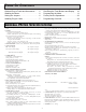
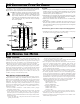
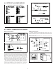
4.4 SETPOINT (ALARMS) WIRING
SETPOINT PLUG-IN CARD TERMINALS
SINKING OUTPUT LOGIC CARD
SOURCING OUTPUT LOGIC CARD
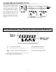
4.5 SERIAL COMMUNICATION WIRING
RS232 Communications
RS232 is intended to allow two devices to communicate over distances up to
50 feet. Data Terminal Equipment (DTE) transmits data on the Transmitted Data
(TXD) line and receives data on the Received Data (RXD) line. Data Computer
Equipment (DCE) receives data on the TXD line and transmits data on the RXD
line. The meter emulates a DTE. If the other device connected to the meter also
emulates a DTE, the TXD and RXD lines must be interchanged for
communications to take place. This is known as a null modem connection. Most
printers emulate a DCE device while most computers emulate a DTE device.
Some devices cannot accept more than two or three characters in succession
without a pause in between. In these cases, the meter employs a busy function.
As the meter begins to transmit data, the RXD line (RS232) is monitored to
determine if the receiving device is “busy”. The receiving device asserts that it
is busy by setting the RXD line to a space condition (logic 0). The meter then
suspends transmission until the RXD line is released by the receiving device.
RS485 Communications
The RS485 communication standard allows the connection of up to 32
devices on a single pair of wires, distances up to 4,000 ft. and data rates as high
as 10M baud. The same pair of wires is used to both transmit and receive data.
RS485 is therefore always half-duplex, that is, data cannot be received and
transmitted simultaneously.
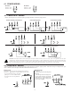
Terminal Block Connection Figure
Terminal Block Connection Figure
Extended Comms Connection Figure
Extended Comms Connection Figure