User’s Guide Shop online at www.omega.com e-mail: info@omega.
OMEGAnet ® Online Service www.omega.com Internet e-mail info@omega.com Servicing North America: USA: ISO 9001 Certified Canada: One Omega Drive, P.O. Box 4047 Stamford CT 06907-0047 TEL: (203) 359-1660 e-mail: info@omega.com 976 Bergar Laval (Quebec) H7L 5A1, Canada TEL: (514) 856-6928 e-mail: info@omega.
Contents INTRODUCTION..........................................................................1 OVERVIEW................................................................................................ 1 W HAT ’S INCLUDED ................................................................................ 1 FACTORY DEFAULT SETTINGS ............................................................ 1 CARD SETUP ..............................................................................2 RS-485 ENABLE M ODES.......
APPENDIX C - ELECTRICAL INTERFACE...................................17 RS-232..................................................................................................... 17 RS-422..................................................................................................... 17 RS-485..................................................................................................... 18 APPENDIX D - ASYNCHRONOUS COMMUNICATIONS ...............19 APPENDIX E - SILK-SCREEN .......................
Introduction Introduction Overview The OMG-ULTRA COMM+2.PCI is a two channel PCI Bus serial I/O adapter for the PC and compatibles. It provides two field selectable RS-232/422/485 serial ports supporting data rates up to 460.8K bps. Configure both ports as RS-232 for standard serial COM: port requirements. Choose the RS-422 mode for long distance device connections up to 4000ft. where noise immunity and high data integrity are essential.
Card Setup Card Setup In all cases J1x refers to settings for the first port and J2x refer to settings for the second port. RS-485 Enable Modes RS-485 is ideal for multi-drop or network environments. RS-485 requires a tri-state driver that will allow the electrical presence of the driver to be removed from the line. The driver is in a tri-state or high impedance condition when this occurs. Only one driver may be active at a time and the other driver(s) must be tri-stated.
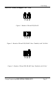
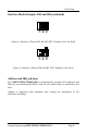
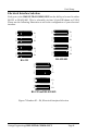
Card Setup AT RT NE Interface Mode Examples J1D – J4D AT RT NE Figure 1- Headers J1B and J2B, RS-422 AT RT NE Figure 2 - Headers J1B and J2B, RS-485 ‘Auto’ Enabled, with ‘No Echo’ Figure 3 - Headers J1B and J2B, RS-485 ‘Auto’ Enabled, with ‘Echo’ Omega Engineering OMG-ULTRA COMM+2.
Card Setup AT RT NE Interface Mode Examples J1B and J2B (continued) AT RT NE Figure 4 - Headers J1B and J2B, RS-485 ‘RTS’ Enabled, with ‘No Echo’ Figure 5 - Headers J1B and J2B, RS-485 ‘RTS’ Enabled, with ‘Echo’ Address and IRQ selection The OMG-ULTRA COMM+2.PCI is automatically assigned I/O addresses and IRQs by your motherboard BIOS. Only the I/O address may be modified by the user. Adding or removing other hardware may change the assignment of I/O addresses and IRQs.
Card Setup Line Termination Typically, each end of the RS-485 bus must have line terminating resistors (RS-422 terminates at the receive end only). A 120-ohm resistor is across each RS-530/422/485 input in addition to a 1K ohm pull-up/pull-down combination that biases the receiver inputs. Headers J1A and J2A allow the user to customize this interface to their specific requirements. Each jumper position corresponds to a specific portion of the interface. If multiple OMG-ULTRA COMM+2.
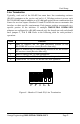
Card Setup Electrical Interface Selection E3 E4 Port 1 RS-232 RS-422 E4 E2 RS-232 RS-232 E3 E1 RS-422 RS-422 E2 Port 2 Port 2 Port 1 RS-232 E1 RS-422 Each port on the OMG-ULTRA COMM+2.PCI has the ability to be used in either RS-232 or RS-422/485. This is selectable via four 24 pin DIP-shunts at E1-E4. Please use the following illustration to aid in the configuration of your electrical interface.
Card Setup Clock Modes The OMG-ULTRA COMM+2.PCI employs a unique clocking option that allows the end user to select from divide by 4, divide by 2 and divide by 1 clocking modes. These modes are selected at Headers J1C through J4C. DIV1 DIV2 DIV4 To select the Baud rates commonly associated with COM: ports (i.e. 2400, 4800, 9600, 19.2, … 115.2K Bps ) place the jumper in the divide by 4 mode (silk-screen DIV4).
Card Setup Baud Rates and Divisors for the ‘Div1’ mode The following table shows some common data rates and the rates you should choose to match them if using the adapter in the ‘Div1’ mode. For this Data Rate 1200 bps 2400 bps 4800 bps 9600 bps 19.2K bps 57.6 K bps 115.2 K bps 230.4K bps 460.8K bps Choose this Data Rate 300 bps 600 bps 1200 bps 2400 bps 4800 bps 14.4K bps 28.8K bps 57.6 K bps 115.
Card Setup Baud Rates and Divisors for the ‘Div2’ mode The following table shows some common data rates and the rates you should choose to match them if using the adapter in the ‘Div2’ mode. For this Data Rate 1200 bps 2400 bps 4800 bps 9600 bps 19.2K bps 38.4K bps 57.6 K bps 115.2 K bps 230.4 K bps Choose this Data Rate 600 bps 1200 bps 2400bps 4800 bps 9600 bps 19.2K bps 28.8K bps 57.6 K bps 115.
Installation Installation Operating System Installation DOS Refer to the ‘PCI.txt’ file found in the \DOS\PCI sub-directory on the supplied Serial Utilities Diskette. Windows 3.1x Refer to the Win3x.hlp file found in the \Windows\3.1x sub-directory on the supplied Serial Utilities Diskette. Windows 95 Refer to the PCI.hlp file found in the \Windows\95 sub-directory on the supplied Serial Utilities Diskette. Windows NT Refer to the PCI.hlp file found in the \Windows\NT sub-directory on the supplied Seria
Technical Description Technical Description The Omega Engineering OMG-ULTRA COMM+2.PCI provides a PCI interface adapter with 2 asynchronous serial ports providing a versatile interface, field selectable as RS-232 for modems, printers and plotters, as well as RS-422/485 for industrial automation and control applications. The OMG-ULTRA COMM+2.PCI utilizes the 16550 UART. This chip features programmable baud rates, data format, interrupt control and a 16-byte input and output FIFO.
Technical Description software designer with a challenge to identify the source of the interrupt. The software designer frequently used a technique referred to as ‘round robin polling’. This method required the interrupt service routine to ‘poll’ or interrogate each UART as to its interrupt pending status. This method of polling was sufficient for use with slower speed communications, but as modems increased their through put abilities this method of servicing shared IRQs became inefficient.
Technical Description RS-422/485 Signal GND TX + TXRTS+ RTSRX+ RXCTS+ CTS- Name Ground Transmit Data Positive Transmit Data Negative Request To Send Positive Request To Send Negative Receive Data Positive Receive Data Negative Clear To Send Positive Clear To Send Negative Omega Engineering OMG-ULTRA COMM+2.
Specifications Specifications Environmental Specifications Specification Temperature Range Humidity Range Operating 0º to 50º C (32º to 122º F) 10 to 90% R.H. Non-Condensing Storage -20º to 70º C (-4º to 158º F) 10 to 90% R.H. Non-Condensing Manufacturing . • All Omega Engineering Printed Circuit boards are built to U. L. 94V0 rating and are 100% electrically tested. These printed circuit boards are solder mask over bare copper or solder mask over tin nickel.
Appendix A - Troubleshooting Appendix A - Troubleshooting A Serial Utility Diskette is supplied with the Omega Engineering adapter and will be used in the troubleshooting procedures. By using this diskette and following these simple steps, most common problems can be eliminated without the need to call Technical Support. 1. Identify all I/O adapters currently installed in your system. This includes your on-board serial ports, controller cards, sound cards etc.
Appendix B - How To Get Assistance Appendix B - How To Get Assistance Please refer to Appendix A - Troubleshooting prior to calling Technical Support. 1. Read this manual thoroughly before attempting to install the adapter in your system. 2. When calling for technical assistance, please have your user manual and current adapter settings. If possible, please have the adapter installed in a computer ready to run diagnostics.
Appendix C – Electrical Interface Appendix C - Electrical Interface RS-232 Quite possibly the most widely used communication standard is RS-232. This implementation has been defined and revised several times and is often referred to as RS-232 or EIA/TIA-232. The IBM PC computer defined the RS-232 port on a 9 pin D sub connector and subsequently the EIA/TIA approved this implementation as the EIA/TIA-574 standard.
Appendix C – Electrical Interface RS-485 RS-485 is backwardly compatible with RS-422; however, it is optimized for partyline or multi-drop applications. The output of the RS-422/485 driver is capable of being Active (enabled) or Tri-State (disabled). This capability allows multiple ports to be connected in a multi-drop bus and selectively polled. RS-485 allows cable lengths up to 4000 feet and data rates up to 10 Megabits per second. The signal levels for RS-485 are the same as those defined by RS-422.
Appendix D - Asynchronous Communications Appendix D - Asynchronous Communications Serial data communications implies that individual bits of a character are transmitted consecutively to a receiver that assembles the bits back into a character. Data rate, error checking, handshaking, and character framing (start/stop bits) are pre-defined and must correspond at both the transmitting and receiving ends.
Appendix E - Silk-Screen Appendix E - Silk-Screen 5.0" 4.2" Omega Engineering OMG-ULTRA COMM+2.
Warranty Appendix F - Compliance Notices Federal Communications Commission Statement FCC - This equipment has been tested and found to comply with the limits for Class A digital device, pursuant to Part 15 of the FCC Rules. These limits are designed to provide reasonable protection against harmful interference when the equipment is operated in a commercial environment.
WARRANTY/DISCLAIMER OMEGA ENGINEERING, INC. warrants this unit to be free of defects in materials and workmanship for a period of 13 months from date of purchase. OMEGA’s WARRANTY adds an additional one (1) month grace period to the normal one (1) year product warranty to cover handling and shipping time. This ensures that OMEGA’s customers receive maximum coverage on each product. If the unit malfunctions, it must be returned to the factory for evaluation.
Where Do I Find Everything I Need for Process Measurement and Control? OMEGA…Of Course! Shop online at www.omega.