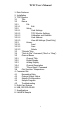
TCIC User’s Manual 1. Main Features 2. Installation 3. TCIC-Monitor 3.1 Title 3.2 Menus 3.2.1 File 3.2.1.1 Exit 3.2.2 Setup 3.2.2.1 Card Settings 3.2.2.2 TCIC-Monitor Settings 3.2.2.3 Calibration and Defaults 3.2.2.4 Card Address 3.2.2.5 View All Settings (Read Only) 3.2.3 Library 3.2.3.1 Load 3.2.3.2 Save 3.2.3.3 Delete 3.3 "Outputs" Box 3.4 "Save to File" Command ('Start' or 'Stop') 3.5 Channel Boxes 3.5.1 Channel Title 3.5.2 Digital Display 3.5.3 Analog Display 3.5.4 Channel Description 3.5.
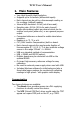
TCIC User’s Manual 1. Main Features • Very High Speed & High Resolution. • Supports up to 8 channels (differential inputs). • Each channel can be set for a thermocouple reading or for a voltage (millivolt) reading. • Internal A/D resolution: 24 bit (not all are used). • Sampling rate: 400 Hz (50 Hz for each channel). • Single opto-isolated output per channel which can be used as a set-point (alarm etc.) or as a general purpose output. • Conversion tables are on board to enable stand-alone operation.
TCIC User’s Manual Setpoints Each channel may be defined as a setpoint, which means that the corresponding output will turn on upon crossing some level. The setpoint user-defined selection also controls the direction of the ‘setpoint indication’; that is, turn the output on upon crossing the limit either upwards or downwards. In other words, the direction of the trigger is user-defined. Likewise, the user may define a hysteresis behavior, e.g.
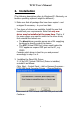
TCIC User’s Manual 2. Installation (The following description refers to Windows XP. Obviously, on another operating system it might be different.) 1. Make sure that all package files have been copied – and unzipped if necessary – to your hard disk. 2. Two types of drivers are available. Install the one that meets best your requirements. Note that only one driver may be installed at the same time. That is, if for some reason you want to switch to the other driver, first uninstall the retired one.
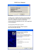
TCIC User’s Manual Click Finish. 3.2 Disconnect or disable the internet communication if such exists. The reason for that is that there are cases where the installation procedure automatically communicates with manufacturer’s site, which might lead to wrong operation. 3.3 Connect the TCIC card to your PC. 3.4 The ‘Found New Hardware Wizard’ appears.
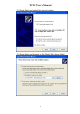
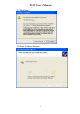
TCIC User’s Manual 3.5 Press Next and select the second option: 3.
TCIC User’s Manual 3.7 Click Next… 3.
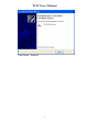
TCIC User’s Manual Click Finish – that’s it! 8
TCIC User’s Manual 4. Installing the VCP (Virtual COM Port) Driver: 4.1 If the Direct DLL Driver is installed, uninstall it as follows: Click: Start – Control Panel – Add or Remove Programs – FTDI FTD2XX USB Drivers – Change/Remove Disconnect all TCIC boards from the USB port and click Continue… Click Finish. 4.2 Connect the TCIC card to your PC.
TCIC User’s Manual 4.3 The ‘Found New Hardware Wizard’ appears. Select the last option like this: 4.
TCIC User’s Manual 4.5 Press Next and browse to the VCP driver folder: 4.
TCIC User’s Manual Click ‘Finish’ – that’s it! Notes 1. It might occur that the wizard will return to step 4.3, requiring to repeat the process. This is normal, just repeat steps 4.3-4.6. 2. The package includes also an RS232 terminal found on the Web, called Termite, through which the TCIC may be communicated when the VCP driver is installed. Termite (http://www.compuphase.com/software_termite.htm) is freeware, yet it is easy to use and easy to configure.
TCIC User’s Manual 3. TCIC-Monitor The TCIC-Monitor utility is an initial setup tool and a smart data logger package for monitoring & collecting readings in high speed, including graphic mode display. The TCIC-Monitor works with both driver types (refer to section 1 - Main Features / Communication). It detects which driver type (direct or VCP) is installed and communicates with the card(s) using that driver (the type of the driver detected is reported in the title).
TCIC User’s Manual The markings in the screenshot below show the section where each part of the display is described.
TCIC User’s Manual 3.1 Title This main title shows the versions of the TCIC-Monitor and of the card. For example, the title in the above screenshot indicates that the version of the TCIC-Monitor is 1.03, while card’s version is 2.01. 3.2 Menus The menus enable various operations, as described below. 3.2.1 File 3.2.1.1 Exit Leaves the TCIC-Monitor program. 3.2.2 Setup 3.2.2.1 Card Settings Adjusts the settings that reside in the card (on its non-volatile memory).
TCIC User’s Manual The settings in detail: Common Setting The following is a common setting for all the channels: Temperature Unit: °C / °F Selects the temperature unit for all channels whose ‘Input Type’ is defined as a thermocouple, i.e., TC-E, TC-J, TC-K, TCR, TC-S, or TC-T. In other words, this setting has no effect on channels whose ‘Input Type’ is mV (or None). Channel Settings The following are individual settings for each channel: Channel Name: ...
TCIC User’s Manual Output Mode: SP-Auto / SP-Latch / Manual This is actually ‘output x’ setting rather than ‘channel x’ setting. This setting defines the nature of output x (x=1,2,...,8): Roughly speaking, output x may be either a ‘setpoint indicator’ of channel x, or a manual output with no relation to channel x (nor any other channel). ‘Manual output’ simply means that the output can be turned on or off directly by the host PC by simple software commands.
TCIC User’s Manual Set Points Switch On: ... Defines the limit that upon its crossing output x will go high (on) signaling a ‘setpoint indication’. Off: ... 1. Defines the direction of temperature change that will trigger the indication: Off < On means indication upon crossing the On limit upwards. Off > On means indication upon crossing the On limit downwards. 2. When Output Mode = ‘SP-Auto’, the Off limit plays one more role: It defines the hysteresis, i.e.
TCIC User’s Manual Example 4: Output Mode = ‘SP-Latch’, ‘On’ = 100°, ‘Off’ = 110°. The output will go high (on) when the temperature falls from 101° to 100°, and stay high (regardless of any temperature change) until manually turned off. Note that – as Output Mode = ‘SP-Latch’ – the only meaning of ‘Off’ = 110° is to set the direction, as 110° > 100°. Specifying ‘Off’ = 120° will give the same effect! 3.2.2.2 TCIC-Monitor Settings Adjusts the settings that reside in the PC (i.e., in a file).
TCIC User’s Manual Sampling Rate: Max. / 0.5 Sec. / ... seconds The Sampling Rate defines the frequency in which readings are refreshed on the display. There are three options: • Max. – Maximal rate that the card can support. • 0.5 Sec. – One refresh each 0.5 sec. • ... seconds – One refresh each x seconds, where x is user-defined. x should be at least 0.5 and at most 1000. Channel Settings The following are individual settings for each channel: Channel Name: ... The user may assign a name to each channel.
TCIC User’s Manual 3.2.2.3 Calibration and Defaults Change Calibration The TCIC is factory programmed with the value of the on board reference voltage (1.25V). However, this default 1.25V value may be re-defined in the range 1.2375V to 1.2625V, that is 1.25V ±1%. In order to find out the voltage, use a high resolution DVM (at least 5.5 digits), and measure between ‘GND’ and ‘COM’ in the screw terminal (CONN1 or CONN2). Click ‘Change Calibration’ and enter your measured new value.
TCIC User’s Manual 3.2.3 Library There is a ‘settings library’ on the PC disk in which all settings may be stored - both Card Settings (section 3.2.2.1) and TCIC-Monitor Settings (section 3.2.2.2). The library files reside in the subfolder TCIC_Lib under the installation folder, for example: C:\Program Files\IMS\TCIC-MONITOR\TCIC_Lib 3.2.3.1 Load Loads a setting set from the library. Once you want the loaded set to take effect, click the ‘Save Settings & Exit’ button.
TCIC User’s Manual 3.4 "Save to File" Command ('Start' or 'Stop') The "Save to File" function enables recording card’s readings in a text file. Upon clicking "Start Save to File" the program suggests an automatic file name, based on the current time & date. Either accept this suggested name, or change it; then click ‘Save’. The recording operation goes on until you press the same button again ("Stop Save to File"), or exit the TCIC-Monitor.
TCIC User’s Manual 3.6 Cold Junction Temperature Displays the temperature of the cold junction, which is essential for the CJC (Cold Junction Compensation). The value of the cold junction temperature is meaningful only when the Input Type is some thermocouple; i.e., it’s irrelevant in case the Input Type is mV (or, of course, None).
TCIC User’s Manual 4. Command Set The communication with the TCIC is via USB (standard), or RS232 or RS485 (optional). Notes 1. After the TCIC has been powered-on, user application software should send a single null (0x00) character to the TCIC, prior to commencing regular communications. 2. There is one more command (card selection in a multi-card system), described in the next section (section 5). 4.
TCIC User’s Manual ‘T’ Returns the board (Cold Junction) in ºC or ºF, whatever was selected in Card settings, plus CR/LF. The value is padded to have a fixed length of 8 characters, so the string has a fixed length of 8 characters (excluding the CR/LF). ‘O’ (upper case letter O) The TCIC returns a string of the form 11110000 plus CR/LF, indicating the actual status of the output switches 1-8. ‘0’ = off, ‘1’ = on. ‘<’ The TCIC returns a string that includes the following items: 1.
TCIC User’s Manual 4.2 Change Output Status The one-character ‘a’ command turns output #1 off. The one-character ‘A’ command turns output #1 on. Similarly, the one-character ‘b’ through ‘h’ and ‘B’ through ‘H’ commands turn the other channels (2-8) off or on, respectively.
TCIC User’s Manual 4.3 Setpoint Configuration The ‘switch on’ & ‘switch off’ limits define the points where the output will go on and, possibly, back off. The relation between the ‘switch on’ limit and the ‘switch off’ limit defines the direction of the mechanism: ’Switch on’ limit > ‘Switch off’ limit: trigger on upwards change When current reading is larger than 'switch on' limit, output goes on. ٠ If the channel is defined as ‘Latch’, the output remains on until turned off manually.
TCIC User’s Manual ‘S’ The TCIC returns a string containing actual 8 ‘switch on’ limits, each followed by a tab (0x09). The end of the string is followed by CR/LF. Each value is padded to have a fixed length of 8 characters, so the string has a fixed length of 72 characters (excluding the CR/LF). “Switch Off” Limit ‘$a’ or ‘$b’ through ‘$h’ Sets the ‘switch off’ limit for the specified channel (1-8). PC must send channel’s letter and a string representing a floating point value in the range -2000.
TCIC User’s Manual 4.4 Sample Program The sample program is an improved version of Microsoft’s example “Using the Comm Port”. This is a basic VB-Net program that clearly shows how to communicate with the card. The sample program works with both driver types (refer to section 1 - Main Features / Communication). It detects which driver type (direct or VCP) is installed and communicates with the card using that driver (the type of the driver detected is reported in the title).
TCIC User’s Manual 4.5 Troubleshooting Q. I can communicate with the TCIC when it is located in COM1 through COM9, but when it is in COM10 or more, my application does not work. The TCIC-Monitor, however, works fine. A. Opening COM port 10 or above is done differently: Prefix "\\.\" to its name. For example: In C: CreateFile( "\\\\.\\COM10",...) In VB.Net: ' Creates a COM Port stream handle Dim COM_Name As String = "COM" & miPort.ToString If miPort > 9 Then COM_Name = "\\.\COM" & miPort.
TCIC User’s Manual 5. Multi-Card System This section is relevant only for the TCIC with the RS485 communication option. Introduction The TCIC’s RS485 communication option supports multi-card systems. In order to utilize this feature, two TCIC operations are required: • Card configuration • Card selection Card configuration – carried out by the TCIC-Monitor utility (see section 3.2.2.4) – sets a card’s address to one of 26 options.
TCIC User’s Manual One Card System When a system includes only one card, neither configuration nor selection is required, as the card is factory defaulted to address ‘a’. Indeed, if a card has been configured to some non-‘a’ address and later it is required as a single card, you may re-configure it to address ‘a’, eliminating the need for the selection function in your application. This is the only case that a card is configured to address ‘a’.
TCIC User’s Manual Communication Protocol There are 26 allowable addresses, referenced by the lower case letters a-z. The address ‘a’ is a special address: every board will respond to this address. In single board RS485, RS232 and USB applications, the board will always be given the address ‘a’, which is also the factory set default. Selecting the board To SELECT a TCIC board, the ‘:’ command is used, followed by the address character. (A CR character is not required). E.g.
TCIC User’s Manual 6. USB, RS232 & RS485 In addition to USB, The TCIC has an option for both full-duplex RS232 and half-duplex RS485 interfaces. These are brought out on CONN6, a 9 way ‘D’ type connector. The pin-out is as follows: CONN6 PIN 1 2 3 4 5 6 7 8 9 FUNCTION RS485RS232 TX (out of TCIC) RS232 RX (into TCIC) NC SIGNAL GROUND RS485+ NC NC NC I.e.
TCIC User’s Manual POWER SUPPLY Using an external power supply is optional on USB* applications but essential for RS232 and RS485 applications. • When used, the external power supply should be connected to the 5V connector (CONN3). • Near this 5V connector there is the 'LK1' jumper, and rightwards there is the LK5 jumper: * Option 1: 5V from the USB port Put the 'LK1' & ‘LK5’ jumpers in the 'USB' side. * Option 2: External 5V supply Put the ‘LK1’ jumper in the 'DC JACK' side.
TCIC User’s Manual 7. Specifications 7.1 Power Supply 5.0 VDC ±5% from either external supply via DC jack or from USB Bus, jumper selectable. 7.2 Communication Ports 7.2.1 USB Either USB bus powered or locally powered. Compatible with USB 2.0 and USB 1.1. Up to 921,600 baud using either direct or VCP (Virtual COM Port) driver. 7.2.2 RS232/RS485 (option) Available on a 9 way D connector.
TCIC User’s Manual 7.4 Thermocouple Types The following thermocouple types and temperature ranges are supported by onboard ITS-90 polynomial conversion functions: Thermocouple Type Range ˚C Accuracy ˚C * J K E R S T -210 to 1200 -200 to 1372 -200 to 1000 -50 to 1768 -50 to 1768 -200 to 400 ± 1.5 ± 1.5 ± 1.5 ± 2.0 ± 2.0 ± 1.5 Resolution ˚C based on 1uVrms noise 0.019 0.024 0.015 0.125 0.143 0.
TCIC User’s Manual 8. LabVIEW Sample The LabVIEW sample was created with LabVIEW 6.1 using the VCP (Virtual COM Port) driver. Figure #1 shows the screen that the LabVIEW sample produces, that is, virtual thermometers of all the eight channels, and a graph of one of these channels (user selectable). Here is an explanation of the LabVIEW sample & how it might be used: The included sample LabVIEW ‘vi’ file enables users of LabVIEW to quickly start acquiring data from the TCIC.
TCIC User’s Manual Figure #1 – output screen of the LabVIEW sample Figure #2 – LabVIEW’s MAX (Measurement and Automation Explorer) 40