MADE IN User’s Guide Shop online at omega.com e-mail: info@omega.com For latest product manuals: omegamanual.
OMEGAnet ® Online Service omega.com Internet e-mail info@omega.com Servicing North America: U.S.A.: ISO 9001 Certified Canada: One Omega Drive, Box 4047 Stamford, CT 06907-0047 Tel: (203) 359-1660 e-mail: info@omega.com 976 Bergar Laval (Quebec) H7L 5A1, Canada Tel: (514) 856-6928 e-mail: info@omega.ca FAX: (203) 359-7700 FAX: (514) 856-6886 For immediate technical or application assistance: U.S.A.
A2400 USERS MANUAL REVISED: 4/17/95 OMEGA ENGINEERING ONE OMEGA DRIVE P. O. BOX 4047 STAMFORD, CT 06907 PHONE: 1-800-DAS-IEEE FAX: 203-359-7990 e-mail: das@omega.com www.omega.com The information in this publication has been carefully checked and is believed to be accurate; however, no responsibility is assumed for possible inaccuracies or omissions.
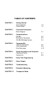
TABLE OF CONTENTS CHAPTER 1 CHAPTER 2 CHAPTER 3 CHAPTER 4 CHAPTER 5 Getting Started Quick Hook-Up Default Mode 1-3 1-4 Functional Description Block Diagram 2-1 Communications RS-485 Multi-party Connection RS-485 Multidrop System 3-2 3-3 3-4 Command Set Table of Commands User Commands Error Messages 4-6 4-6 4-13 Setup Information and Command Command Syntax Setup Hints 5-1 5-8 CHAPTER 6 Delay Time Programming CHAPTER 7 Power Supply CHAPTER 8 Troubleshooting CHAPTER 9 Extended Addressing
Chapter 1 Getting Started Introduction This manual describes the function and application of the Radio Modem Interface Module (A2400). The A2400 provides an intelligent interface between radio modems available from many manufacturers and devices designed to operate on a bi-directional RS-485 serial bus. Although the A2400 has been designed specifically for our family of industrial I/O modules, it may also be used with other RS-485 devices. Figure 1.1 depicts a typical application that incorporates A2400’s.
Getting Started 1-2 A2400 is to control the slave transmitter to allow multiple slave sites. Figure 1.1 System Overview. Leased Lines This manual has been written with emphasis on radio modems. However, the A2400’s may be used just as effectively with leased telephone lines. Typically, leased lines do not have dial-up capability and some means of addressing and multiplexing must be employed if multiple stations are used.
Getting Started 1-3 Getting Started To get your A2400 up and running for an initial check-out, connect the unit to a power supply and terminal as shown in Figure 1.2. The power supply can be any dc source from 10 to 30 volts, capable of 1 Watt of power. The terminal can be any RS-232 dumb terminal set for 300 baud. A computer configured as a terminal can also be used. Be sure to ground the DEFAULT* pin. Figure 1.2 A2400 Quick Hookup. After checking the connections, power up the A2400.
Getting Started 1-4 This message is terminated with a carriage return. If the response message cannot be obtained, re-check all the wiring, making sure that the proper power is on the A2400 connector and that the DEFAULT* line is shorted to the GND pin. The terminal must be set to 300 baud. If, after several attempts, the response message does not appear, refer to Chapter 8 Troubleshooting in this manual.
Getting Started 1-5 values (NULL, CR, $, #, {, }). A dummy address must be included in every command for proper responses. Setup information in an A2400 may be changed at will with the SetUp (SU) command. Baud rates and parity setups may be changed without affecting the Default values of 300 baud and no parity. When the DEFAULT* pin is released, the module automatically performs a program reset and configures itself to the baud rate and parity stored in the setup information.
Chapter 2 Functional Description Block Diagram The A2400 is an RS-232/RS-485 converter specifically designed to interface D series RS-485 modules to radio modems. To this end the A2400 provides three functions: 1) Perform the RS-232 to RS-485 electrical conversion. 2) Control the data direction of the RS-485 bus. 3) Create hand-shaking signals to control the modem. A simplified block diagram of the A2400 is illustrated in Figure 2.1.
Functional Description 2-2 DEFAULT +5V RTS CTS RX RX TX MICROPRCESSOR TX UART +5 EEPROM 5.6K DO0/RTS Figure 2.1 A2400 Block Diagram.
Functional Description 2-3 Pinout 1) TRANSMIT This is the RS-232 Transmit output from the A2400. This pin is normally connected to the Receive input of a modem. This output is also used to connect to a terminal or computer to configure the A2400 2) RECEIVE This is the RS-232 Receive input of the A2400. This pin is normally connected to the Data Output of a radio modem. This input is also used to connect to a terminal or computer to configure the A2400 3) RTS RS-232 Request To Send output.
Functional Description 2-4 bus. This bus connects to multidrop RS-485 devices such as D series modules. 8) (G)DATA- This is the negative polarity of the differential RS-485 bus. 9) (R)V+ volts dc. A2400 power connection. The A2400 operates on 10 to 30 10) (B)GND This is the ground connection common to all circuits. The A2400 does not have isolation between power and the two communications ports. Note that pins 7 through 10 are designated Y, G, R, and B respectively.
Functional Description 2-5 reaching the RS-485 bus. The first operation performed on the modem data is to check for noise and framing errors. If either condition exists, the bad character is re-formatted as a null character (ASCII $00). Since the null is not a legal character for use as an address in the modules, transmitting a null is preferable to aborting the character when an error is detected. This cuts down on the possibility of a module being incorrectly addressed.
Functional Description 2-6 addressed command and it responds back with information on the bus. The A2400 receives this information and places it in a buffer that can hold up to 96 characters. The parity of received characters is ignored. As soon as a character is received, the A2400 starts a timing sequence to control the modem transmitter. Three user-programmable timers, T1, T2, and T3 control the data flow. See Figure 2.2 . Figure 2.2 Programmable Delay Times.
Functional Description 2-7 T1 As soon as the A2400 detects a character in the RS-485 receive buffer, time delay T1 is activated. This is a dead time to allow the host to prepare for the receipt of a message. This is particularly important when a simplex connection is used, where the send and receive data is transmitted on the same frequency. During this time the A2400 creates no control output, but any data received on the RS-485 port is stored in the receive buffer.
Chapter 3 Communications Introduction The A2400 modules have been carefully designed to be easy to interface to all radio modems and many leased-line modems. All communications to and from the modules are performed with printable ASCII characters. This allows the information to be processed with string functions common to most highlevel languages such as BASIC. The ASCII format makes system debugging easy with a dumb terminal.
Communication 3-2 improper command prompt or address is transmitted. The table below lists the timeout specification for each command assuming that delay times T1, T2, T3 = 0: Table 3.1 Response Timeout Specifications. Mnemonic DO, OC, CC, RD, REA, RID, RLP, RS, RSP, RSU, RT1, RT2, RT3, WE EA, ID, LP, RID, RR, SP, SU, T1, T2, T3 Timeout ≤ 10 ms ≤ 100 ms The timeout specification is the turn-around time from the receipt of a command to when the module starts to transmit a response.
Communication 3-3
Communication 3-4 RS-485 Multidrop System Figure 3.1 illustrates the wiring required for multiple-module RS-485 system. Notice that every module has a direct connection to the A2400. Any number of modules may be unplugged without affecting the remaining modules. Each module must be setup with a unique address and the addresses can be in any order. All RS-485 modules must be setup for no echo to avoid bus conflicts (see Setup).
Communication 3-5 becomes an important consideration. The GND wire is used both as a power connection and the common reference for the transmission line receivers in the modules. Voltage drops in the GND leads appear as a common-mode voltage to the receivers. The receivers are rated for a maximum of -7V. of common-mode voltage. For reliable operation, the common mode voltage should be kept below -5V.
Chapter 4 A2400 Command Set The A2400 operates with a simple command/response protocol to control all module functions. A command must be transmitted to the A2400 by the host computer or terminal before the A2400 will respond with useful data. A module can never initiate a communications sequence. A list of available commands and a sample format for each command is listed in Table 4.1. The following text describes the protocol normally used with the A2400.
Command Set 4-2 All commands must be terminated by a carriage return character (ASCII $0D). In all command examples in this text the carriage return is either implied or denoted by the symbol ‘CR’. Data Structure Many commands require additional data values to complete the command definition as shown in the example commands in Table 4.1. The particular data necessary for these commands is described in full in the complete command descriptions. Write Protection Some commands listed in Table 4.
Command Set 4-3 A command/response sequence is not complete until a valid response is received. The host may not initiate a new command until the response from a previous command is complete. Failure to observe this rule will result in communications collisions.
Command Set 4-4 interprets a command, it looks for the two extra characters and assumes that it is a checksum. If the checksum is not present, the module will perform the command normally. If the two extra characters are present, the module will calculate the checksum for the message. If the calculated checksum does not agree with the transmitted checksum, the module will respond with a ‘BAD CHECKSUM’ error message and the command will be aborted. If the checksums agree, the command will be executed.
Command Set 4-5 Example: Append a checksum to the command $1WE Characters: ASCII hex values: $ 24 1 31 W 57 E 45 Sum (hex addition) 24 + 31 + 57 + 45 = F1 The checksum is F1 (hex).
Command Set 4-6 Each A2400 user command is described in detail following Table 4.1. All of the commands are listed in alphabetical order according to command nomenclature. Table 4.1 A2400 Command Set Command and Definition Typical Command Message Typical Response Message ($ prompt) DO RD REA RID RLP RS RSP RSU RT1 RT2 RT3 WE $1DO01 $1RD $1REA $1RID $1RLP $1RS $1RSP $1RSU $1RT1 $1RT2 $1RT3 $1WE * *+99999.99 *3031 *TANK FARM 1 *7D *31070000 *7B *31070000 *+00100.00 *+00352.00 *+00050.
Command Set 4-7 Command Descriptions All the commands may be used with normal addressing or Extended Addressing unless otherwise noted. Commands that are exclusive to the Extended Address mode are noted near the right hand margin. For example: Closed Channel (CC) (Extended) Closed Channel (CC) (Extended) The Close Channel (CC) command is an Extended Address Mode command that is used to close the communications data channel in an A2400.
Command Set 4-8 To turn the output off you could use the command: Command: Response: $1DO00 * Command: Response: #1DO00 *1DO004E Digital output 0 shares the connector pin with the Alternate RTS. Bit 3 of byte 4 of the SetUp command is used to configure this pin as either digital output or RTS function. See chapter 5 for details. The digital output setting is not stored in nonvolatile memory. If a power failure occurs, the digital output will be 0 upon power up.
Command Set 4-9 Identification (ID) The IDentification command allows the user to write a message into the nonvolatile memory which may be read back at a later time with the Read IDentification (RID) command. It serves only as a convenience to the user and has no affect on the module operation. Any message up to 16 characters long may be stored in memory. Useful information such as the location, calibration data, or model number may be stored for later retrieval. The ID command is write protected.
Command Set 4-10 Open Channel (OC) (Extended) The Open Channel (CC) command is used to open the communications data channel in Extended Address mode. The open channel will allow serial communications data to flow from the A2400’s RS-232 port to a string of RS485 devices. The open communications channel will remain open until a Close Channel (CC) command or Remote Reset (RR) command is received by the device.
Command Set 4-11 In this example the ‘30’ and ‘31’ are the hex ASCII codes for the characters ‘0’ and ‘1’ respectively. The Extended Address is ‘01’. Read Identification (RID) The Read IDentification command reads back the user data stored by the IDentification (ID) command. The ID and RID commands are provided as a convenience to the user to store up to 16 characters of information in the A2400 EEPROM.
Command Set 4-12 Command: Response: #1RR *1RRFF Read Setup (RS or RSU) The read setup command reads back the setup information stored in the A2400’s EEPROM with the SetUp (SU) command. The response to the RS or RSU command is four bytes of information formatted as eight hex characters. The response contains the module’s channel address, baud rate and otherparameters. Refer to the SetUp (SU) command for a list of parameters in the setup message.
Command Set 4-13 Read Time Delay 1 (RT1) The Read Time 1 command reads back the time value stored in EEPROM by T1 command. Command: Response: $1RT1 *+00100.00 Command: Response: #1RT1 *1RT1+00100.00DC Read Time Delay 2 (RT2) The Read Time 2 command reads back the time value stored in EEPROM by the T2 command. Command: Response: $1RT2 *+00500.00 Command: Response: #1RT2 *1RT2+00500.00E1 Read Time Delay 3 (RT3) The Read Time 3 command reads back the time value stored in EEPROM by the T3 command.
Command Set 4-14 The SetUp command requires an argument of eight hexadecimal digits to describe four bytes of setup information. Command: Response: $1SU31070007 * Command: Response: #1SU31070007 *1SU3107000795 Set Time Delay 1 (T1) T1 is a programmable time delay used to control the RTS output. T1 is used to guarantee a dead time between the completion of host transmitted data and the beginning of remote data transmission.
Command Set 4-15 T2 is specified in units of milliseconds with a range of 0 to 2000ms. The time data must be formatted as a plus sign, five decimal digits, a decimal point, and two additional digits: Command: Response: $1T2+00350.00 (Set T2 to 350 ms.) * Command: Response: #1T2+00350.00 (Set T2 to 350 ms.) *1T2+00350.0092 Set Time Delay 3 (T3) T3 is the delay time between the last character transmitted to the host and the trailing edge of RTS signal which turns off the remote transmitter.
Command Set 4-16 Short Prompt (SP) The Short Prompt command allows the user to specify a desired short prompt ASCII character. A two character hexadecimal value is used to define the desired ASCII character prompt. Note: Short Prompt command may be sent to the module in either normal addressing or Extended Addressing mode. The user-defined short form prompt is only recognized by the module when the module is in the Extended Addressing mode. See chapter 7 for details on the Extended Addressing mode.
Command Set 4-17 Command: Response: }01WE *01WE27 If a module is write enabled and the execution of a command results in an error message other than WRITE PROTECTED, the module will remain write enabled until a command is successfully completed resulting in an ‘*’ prompt. This allows the user to correct the command error without having to execute another WE command. ERROR MESSAGES All modules feature extensive error checking on input commands to avoid erroneous operation.
Command Set 4-18 COMMAND ERROR This error occurs when a command is not recognized by the module. Often this error results when a command is sent with lowercase letters. All valid commands use uppercase characters. PARITY ERROR A parity error can only occur if the module is setup with parity on. Usually a parity error results from a bit error caused by interference on the communications line. Random parity errors are usually overcome by simply repeating the command.
Chapter 5 Setup Information/SetUp Command The A2400 features a wide choice of user configurable options which gives them the flexibility to operate on virtually any radio or leased-line modem. The user options include a choice of baud rate, parity, address, and many other parameters. The particular choice of options for a module is referred to as the setup information. The setup information is loaded into the module using the SetUp (SU) command.
SetUp Command 5-2 A typical SetUp command would look like: $1SU31070102 Notice that each byte is represented by its two-character ASCII equivalent. In this example, byte 1 is described by the ASCII characters ‘31’ which is the equivalent of binary 0011 0001 (31 hex). The operand of a SU command must contain exactly 8 hex (0-F) characters. Any deviation from this format will result in a SYNTAX ERROR. For the purposes of describing the SetUp command, ‘bit 7’ refers to the highest-order bit of a byte of data.
SetUp Command 5-3 to communicate with a module with an unknown address is with the Default Mode. The most significant bit of byte 1 (bit 7) must be set to ‘0’. In addition, there are six ASCII codes that are illegal for use as an address. These codes are $00, $0D, $24, $23, $7B, $7D which are ASCII codes for the characters NUL, CR, $, #, {, and }. Using these codes for an address will cause an ADDRESS ERROR and the setup data will remain unchanged.
SetUp Command 5-4 Byte 2 Byte 2 is used to configure some of the characteristics of the communications channel; linefeeds, parity, and baud rate. Linefeeds The most significant bit of byte 2 (bit 7) controls linefeed generation by the module. This option can be useful when using the module with a dumb terminal. All responses from the modules are terminated with a carriage return (ASCII $0D). Most terminals will generate a automatic linefeed when a carriage return is detected.
SetUp Command 5-5 changed, a module reset must occur. A reset is performed by sending a Remote Reset (RR) command or powering down. This extra level of write protection is necessary to ensure that communications to the module is not accidentally lost. This is very important when changing the baud rate of an RS-232C string. For more information on changing baud rate, refer to Chapter 3. Let’s run through an example of changing the baud rate.
SetUp Command 5-6 Command: Response: $1RR * Up to this point all communications have been sent at 300 baud. The module will not respond to any further communications at 300 baud because it is now running at 9600 baud. At this point the host computer or terminal must be set to 9600 baud to continue operation. If the module does not respond to the new baud rate, most likely the setup data is incorrect. Try various baud rates from the host until the module responds.
SetUp Command 5-7 Byte 3 This byte contains determines which addressing mode will be used. The default value for this byte is ‘00’. Normal addressing The normal addressing mode refers to the D series protocol of using a single ASCII character for a channel address. There are up to 124 possible addresses in this mode.
Chapter 6 Delay Time Programming Each A2400 contains user-programmable delays to properly sequence the transmission of data from a remote radio modem to a host computer. The delays are required to sequence an external transmit enable signal required by most radio modems. The external transmit enable signal most often used is the RS-232 Request to Send (RTS) signal.
Delay Time Programming 6-2 Figure 6.1 Programmable delay times. As described in figure 6.1 the communications sequence assumes a host computer communicating with a module on the RS-485 bus through the A2400. In an idle condition, when no data is present on the communications lines, the A2400 turns its RS-485 transceiver to receive mode and monitors activity on the RS-485 bus.
Delay Time Programming 6-3 the data over the RS-485 bus. This data is normally command data being sent to a module on the bus. When the RS-232 command data is complete, the A2400 immediately turns its RS-485 transceiver back to receive mode and monitors the RS-485 bus. In normal operation the A2400 looks for a D series response prompt character, either a ‘*’ or ‘?’. When a response prompt is received, the A2400 begins the first delay time , T1.
Delay Time Programming 6-4 Command: Response: $1T3+00050.00 * (set T3 to 50 ms.) Time may be set to 1 ms. resolution. The T1, T2, T3 commands are write-protected and must be preceded by a Write Enable (WE) command. The delay times are stored in nonvolatile memory. The delay times are inactive in Default Mode. The delay times stored in the A2400 may be read back with RT1, RT2, and RT3 commands: Command: Response: $1RT1 *+00100.
Chapter 7 Power Supply A2400 modules may be powered with an unregulated +10 to +30Vdc. Power-supply ripple must be limited to 5V peak-to-peak, and the instantaneous ripple voltage must be maintained between the 10 and 30 volt limits at all times. All power supply specifications are referred to the module connector; the effects of line voltage drops must be considered when the module is powered remotely.
Chapter 8 Troubleshooting Symptom: RS-232 Module is not responding to commands 1 Using a voltmeter, measure the power supply voltage at the +Vs and GND terminals to verify the power supply voltage is between +10 and +30Vdc. 2 Verify using an ohmmeter that there are no breaks in the communications data lines. 3 Connect the module to the host computer and power-up each device (module and computer) then using a voltmeter measure the voltage between RECEIVE and GND. This voltage should be approximately - 10Vdc.
Chapter 9 Extended Addressing The A2400 may be configured to a special command format called Extended Addressing. This mode uses a different prompt, either ‘{‘ or ‘}’ to distinguish it from the regular command syntax. The major difference in syntax for the Extended Addressing mode is that it uses a two-character address. A typical command in Extended Address mode would look like this: Command: Response: {01WE * Both the command and response are terminated with carriage returns.
Extended Addressing 9-2 Figure 7.1 Typical system overview.
Extended Addressing 9-3 When the system is initially powered up, the A2400’s are set to the Close Channel condition. This means that no data received by the radio modems will pass to the RS-485 bus at either site. In order to communicate to the modules, one of the A2400’s must be set to the Open Channel condition: Command: Response: {01OC * This command orders the A2400 address ‘01’ to open the ‘data gate’ between the radio modem and the two-module string on the RS-485 bus.
Extended Addressing 9-4 Figure 7.1 shows a very simple system but the same addressing methodmay be used to construct very large systems. Each RS-485 string may handle up to 122 addresses, and up to 14884 A2400’s may have unique addresses. Structured Addressing Even for a relatively small system, it can be advantageous to employ a hierarchical addressing system as used in Fig. 7.1. This is particularly true in systems that consist of many sites that are identical.
Extended Addressing 9-5 All commands that are available with single-byte addressing may be accessed with Extended Addressing, and vice-versa; the only exceptions being the OC and CC commands, which can be used only with Extended Addressing. OC and CC Command Formats Once an A2400 has been configured correctly in Extended Address mode, the only commands necessary for normal operation are the Open Channel (OC) and Close Channel (CC) commands.
Extended Addressing 9-6 This command will close the channel at A2400 #01 and open the channel at A2400 #02. This is the quickest method of opening and closing A2400 channels. It also offers the least amount of data security. A2400 #01 was closed solely upon detecting the ‘{‘ character. There is no confirmation that A2400 #01 is closed. If A2400 #01 missed the ‘{‘ character due to noise, it would remain open, with the possibility of two A2400’s in the open condition, an undesirable state of affairs.
Extended Addressing 9-7 To explicitly close the channel of A2400 #01: Command: Response: {01CC * The response message is a confirmation that the channel has been closed. A higher level of confirmation can be obtained with the long form: Command: Response: }01CC *01CC11 (‘11’ is the checksum) The response confirms that channel ‘01’ has been closed.
Chapter 10 Transparent Mode The A2400 is an RS-232/RS-485 converter designed to provide interface virtually any product to a radio and leased telephone line modems. In normal operation the A2400 is configured to work on the D series protocol, but it may be configured to a special communications mode called the transparent mode. When used in the transparent mode the A2400 module provides an effective radio or leased-line modem interface for equipment that does not use the D series protocol.
Transparent Mode 10-2 The following examples 1 through 4 illustrate the application of the A2400 in the extended mode of operation. The A2400 in transparent mode allows equipment from various sources to be added to a network of D series modules. However the following rules must apply: 1. half duplex communications. 2. 10-bit data format. 3.
Transparent Mode 10-3 Example 2. A2400 networking several RS-232 devices to a host computer. Figure 10.2 A2400 networking several RS-232 devices to a host computer.
Transparent Mode 10-4 Example 3. A2400 interfacing a device with a string of modules. Figure 10.3 A2400 interfacing a laboratory instrument with modules.
Transparent Mode 10-5 Example 4. A2400 interfacing several instruments with a string of modules.
Transparent Mode 10-6 Figure 10.5 Adding secondary control using A2400 modules.
Transparent Mode 10-7 Figure 10.5 shows an application where the user was able to add a back-up or secondary control supervision using the A2400 modules. The original installation of the flow computers and PLC’s were controlled by the control station using Modbus protocol with RS-485. The user was able to use A2400 modules on the RS232 ports of the devices and establish a second control loop The flow computers and PLC’s had addressing capability.
WARRANTY/DISCLAIMER OMEGA ENGINEERING, INC. warrants this unit to be free of defects in materials and workmanship for a period of 13 months from date of purchase. OMEGA’s WARRANTY adds an additional one (1) month grace period to the normal one (1) year product warranty to cover handling and shipping time. This ensures that OMEGA’s customers receive maximum coverage on each product. If the unit malfunctions, it must be returned to the factory for evaluation.
Where Do I Find Everything I Need for Process Measurement and Control? OMEGA…Of Course! Shop online at omega.