User’s Guide Shop online at www.omega.com e-mail: info@omega.
WARRANTY/DISCLAIMER OMEGA ENGINEERING, INC. warrants this unit to be free of defects in materials and workmanship for a period of 13 months from date of purchase. OMEGA’s WARRANTY adds an additional one (1) month grace period to the normal one (1) year product warranty to cover handling and shipping time. This ensures that OMEGA’s customers receive maximum coverage on each product. If the unit malfunctions, it must be returned to the factory for evaluation.
TABLE OF CONTENTS INTRODUCTION ................................................................... 1 BNC-08DI .......................................................................... B1-B16 . . . . . . . . . . . . . . . . . . . . . . . . . . . . . . . . . . . . . . . . . . . . . . . . . . . . . . . . . . . . . . . . . . . . . . . . . . . . . . P2 . . . . . . . . . . . . . . . . . . . . . . . . . . . . . . . . . . . . . . . . . . . . . . . . . . . . . . . . . . . . . . . . . . . . . . . . . . . . . . .
INTRODUCTION The BNC series of signal connection boxes have been designed as universal interfaces for the DAS family of analog I/O boards. The BNC-08DI accepts up to 8 differential pairs of analog inputs while the BNC-16SE and the BNC-16DI can accept up to 64 single ended or 32 differential analog inputs. For user convenience, a variety of I/O signals from the DAS board are brought out to a 37 pin D connector at the front of the enclosure.
BNC-08DI The BNC-08DI incorporates 16 front panel mounted BNC connectors providing up to 8 differential analog inputs to the CIO-DAS family of data acquisition boards. B1-B16 The 16 front panel mounted BNC connectors B1-B16, are routed through the enclosure to the rear panel-mounted 37 D connector P2.
EXTERNAL TRIGGER The EXTERNAL TRIGGER BNC connectors B17 and B18 are provided for applications that require external digital triggering of the data acquisition board. These connectors could also be used in applications requiring synchronization to the digital trigger signal. The digital trigger signal is available on connectors P1-P4 as illustrated in the following diagram.
BNC-16DI The BNC-16DI incorporates 16 front panel mounted BNC’s allowing connection of up to 8 differential analog inputs to the CIO-DAS and PCI family of data acquisition boards. The BNC-16DI can accommodate boards with either 37 or 50 pin I/O connectors; with connector P2 used to interface to data acquisition boards utilizing a 37 pin, D type I/O connector, while connectors P3, P4 and P5 are used to interface to data acquisition boards utilizing a 100 pin I/O connector.
. . P1 The front panel mounted DB37 connector P1 provides a variety of I/O signals, not including the 16 analog input signals from BNC’s B1-B16. Please refer to the P1 CONNECTOR MAP section for a detailed explanation of P1’s connection scheme and signal availability.
EXTERNAL TRIGGER The EXTERNAL TRIGGER BNC connectors B17 and B18 are provided for applications that require external digital triggering of the data acquisition board. These connectors could also be used in applications requiring synchronization to the digital trigger signal. The digital trigger signal is available on connectors P1-P4 as illustrated in the following diagram.
Headers P6 and P7 are factory set to the “1-2” position, pre-configuring B15 and B16 as analog input BNC’s. For those applications which require D/A outputs along with B15 and B16 to be used in the analog input mode; the user can leave B15 and B16 in the analog input mode and access the D/A outputs at connector P1. The following diagram illustrates the connection scheme used to route the D/A output signals from P2-P4 to B15, B16 and P1.
BNC-16SE The BNC-16SE incorporates 16 front panel mounted BNC’s allowing connection of up to 16 single-ended analog inputs to the CIO-DAS and PCI family of data acquisition boards. The BNC-16SE can accommodate boards with either 37 or 50 pin I/O connectors; with connector P2 used to interface to data acquisition boards utilizing a 37 pin D type I/O connector, while connectors P3, P4 and P5 are used to interface to data acquisition boards utilizing a 100 pin I/O connector.
. P1 The front panel mounted DB37 connector P1 provides a variety of I/O signals, not including the 16 analog input signals from BNC’s B1-B16. Please refer to the P1 CONNECTOR MAP section for a detailed explanation of P1’s connection scheme and signal availability.
EXTERNAL TRIGGER The EXTERNAL TRIGGER BNC connectors B17 and B18 are provided for applications that require external digital triggering of the data acquisition board. These connectors could also be used in applications requiring synchronization to the digital trigger signal. The digital trigger signal is available on connectors P1-P4 as illustrated in the following diagram.
Headers P6 and P7 are factory set to the “1-2” position, pre-configuring B15 and B16 as analog input BNC’s. For those applications which require D/A outputs along with B15 and B16 to be used in the analog input mode; the user can leave B15 and B16 in the analog input mode and access the D/A outputs at connector P1. The following diagram illustrates the connection scheme used to route the D/A output signals to from P2-P4 to B15, B16 and P1.
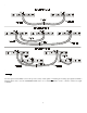
P1 CONNECTOR MAP Connector P1 provides the user with a variety of I/O signals, not including the 16 analog input signals from B1-B16. The following diagram illustrates the connection scheme used to route these signals among connectors P2, P3 and P4 to connector P1. These signals are labeled “PASS” signals (except for the trigger and D/A options as shown) and the user should consult their DAS manual’s I/O connector pin assignment section to verify the actual signals available at the P1 connector.
3 &RQQHFWRU 0DS IRU %1& ', 13
BOARD COMPATIBILITY The BNC-08DI is compatible with the following DAS boards: DAS Boards CIO-DAS801 CIO-DAS802 CIO-DAS802/16 CIO-DAS08-AOH CIO-DAS08-AOL CIO-DAS08-AOM CIO-DAS08-PGA CIO-DAS08-PGH CIO-DAS08-PGL CIO-DAS08-PGM Input Configuration 8 Differential Inputs 8 Differential Inputs 8 Differential Inputs 8 Differential Inputs 8 Differential Inputs 8 Differential Inputs 8 Differential Inputs 8 Differential Inputs 8 Differential Inputs 8 Differential Inputs The BNC-16DI and BNC-16SE are compatible with
INPUT CONFIGURATIONS Each BNC connector of the BNC-08/16DI and the BNC-16SE incorporates programmable, signal conditioning circuitry, which allows the user to connect a wide variety of options including filtering, bypassing, voltage division and termination. For situations where the factory installed shunt resistors RXA or RXB have been removed, solder gaps have been provided to quickly and easily reconnect these portions of the circuit.
Normal R Divider 0 ohm open RXA* 0 ohm 0 ohm RXB* open resistor RXC open resistor RXD open 0 ohm RXE open open RXF *factory installed 0 ohm resistors RC Filter open 0 ohm resistor capacitor 0 ohm open AC Couple capacitor 0 ohm open open open open %1& ', ,QSXW &RQILJXUDWLRQ 16 50 Ohm 0 ohm 0 ohm open open open resistor Bypass 0 ohm 0 ohm 0 ohm capacitor open open
The following diagram illustrates the signal conditioning circuitry of a differential analog input channels used on the BNC-16DI and the BNC-08DI. CH.0 HIGH B1 SG2 R0A P2 CH.0 H 18 37 CH.0 L R0C R0F SG1 R0B R0E R0D RS0 CH.
The following illustrations describe some common differential mode connection methods of the BNC-08/16DI enclosure. These are just a few of the many possible connection methods made possible using the programmable signal conditioning circuits. 1. 2. 3. Diagram A. describes a true differential setup utilizing a pair of coaxial cables. The grounding of the coaxial cable’s shield at the enclosure end of the BNC cable is strictly an option. Diagram B.
BOARD ACCESSIBILITY Accessing the individual BNC input configuration circuits, or headers P6 or P7 (BNC-16SE, BNC16DI only) can be easily accomplished by removing the following hardware: enclosure screws (2), External Trigger nut and washer, and P2 set screws (2).
EC Declaration of Conformity We, ComputerBoards, Inc.
OMEGAnet ® Online Service www.omega.com Internet e-mail info@omega.com Servicing North America: USA: ISO 9001 Certified Canada: One Omega Drive, P.O. Box 4047 Stamford CT 06907-0047 TEL: (203) 359-1660 e-mail: info@omega.com 976 Bergar Laval (Quebec) H7L 5A1, Canada TEL: (514) 856-6928 e-mail: info@omega.
Where Do I Find Everything I Need for Process Measurement and Control? OMEGA…Of Course! Shop online at www.omega.