User’s Guide Conductivity/Resistivity 62.50 uS/cm 25.0°C Shop online at ENTER www.omega.com e-mail: info@omega.
OMEGAnet® Online Service www.omega.com Internet e-mail info@omega.com Servicing North America: USA: One Omega Drive, P.O. Box 4047 Stamford CT 06907-0047 TEL: (203) 359-1660 e-mail: info@omega.com ISO 9001 Certified Canada: 976 Bergar Laval (Quebec) H7L 5A1 TEL: (514) 856-6928 e-mail: info@omega.
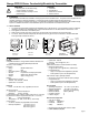
Omega CDTX-90 Series Conductivity/Resistivity Transmitter CAUTION! Contents • 1. 2. 3. 4. • Remove power to unit before wiring input and output connections. Follow instructions carefully to avoid personal injury. Conductivity/Resistivity 62.50 uS/cm 25.0°C Installation Specifications Electrical Connections Menu Functions ENTER 1. Installation CDTX-90 Series transmitters are available in two styles: panel mount and field mount.
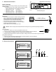
3. Electrical Connections Sensor Selection Select the sensor with a range closest to your process minimum and maximum values. • CDCE-90-001 (0.01 cell): 0.055 to 100 µS (10 kΩ to 18 MΩ) Use the CDCE-90-001 for all resistivity requirements • CDCE-90-01 (0.1 cell): 1 to 1000 µS • CDCE-90-1 (1.0 cell): 10 to 10,000 µS • CDCE-90-10 (10.0 cell): 100 to 200,000 µS • CDCE-90-20 (20.0 cell): 200 to 400,000 µS Wiring Tips: • Do not route sensor cable in conduit containing AC power wiring.
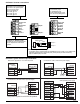
CDTX-90-1 Terminal connections Terminals 3 and 4: Loop Power 12-24 VDC ±10% system power and current loop output. Max. loop impedance: 50 Ω max. @ 12 V 325 Ω max. @ 18 V 600 Ω max.
CDTX-90-2 Terminal Connections Terminals 3 and 4: Loop Power 12-24 VDC ±10% system power and current loop output. Max. loop impedance: 50 Ω max. @ 12 V 325 Ω max. @ 18 V 600 Ω max. @ 24 V Terminals 11-14: Sensor input 11 is conductivity input 12 is temperature input 13 is the isolated signal ground 14 is the sensor earth ground 10 Relay 2 (NO) 9 Relay 2 (COM) 4 System Pwr Loop - 8 Relay 2 (NC) 14 Sensr Gnd (SHIELD) 3 System Pwr Loop + 7 Relay 1 (NO) 13 Iso.
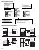
CDTX-90-3 Terminal Connections Terminals 3-6: Loop Power 12-24 VDC ±10% system power and current loop output. Max. loop impedance: 50 Ω max. @ 12 V 325 Ω max. @ 18 V 600 Ω max. @ 24 V 6 Loop 2- 5 Loop 2+ 4 Terminals 11-14: Sensor input 11 is conductivity input 12 is temperature input 13 is the isolated signal ground 14 is the sensor earth ground 10 Output 2- System Pwr Loop - 9 Output 2+ 14 Sensr Gnd (SHIELD) 3 System Pwr Loop + 8 Output 1- 13 Iso. Gnd (BLACK) 2 AUX Power - 12 Temp.
• High setpoint: Output triggers when process is greater than the setpoint. The output will relax when the process moves below the setpoint plus the hysteresis value. Process Hysteresis Low Setpoint Time Relay energized Relay relaxed In the example below: • The output will be 0 pulses/min. when value is less than 5 µS. • The output will be 50 pulses/min. when value is 7.5 µS. • The output will be 100 when value is greater than 10 µS.
CDTX-90 Series Editing Procedure: Step 1. Press and hold ENTER key: • 2 seconds to select the CALIBRATE menu. • 5 seconds to select the OPTIONS menu. Step 2. The Key Code is UP-UP-UP-DOWN keys in sequence. • After entering the Key Code, the display will show the first item in the selected menu. Step 3. Scroll menu with UP or DOWN arrow keys. Step 4. Press RIGHT ARROW key to select menu item to be edited. • The first display element will begin flashing. Step 5.
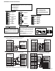
CDTX-90-1 Calibrate Menu Display (Factory settings shown) Select CUSTOM only if you are connecting a certified conductivity sensor. Select STANDARD for all other systems. Cell Constant: Standard > For STANDARD sensors: Select from these options: 0.01, 0.1, 1.0, 10.0 or 20.0. Cell: Standard 1 > For CUSTOM sensors: Enter the precise cell constant from the certificate provided with your sensor, or from the information label on the sensor. Cell: Custom 1.
CDTX-90-1 Options Menu Display (Factory settings shown) Contrast: 3 Cond Decimal: ****.* Description > Adjust the LCD contrast for best viewing. A setting of 1 is lower contrast, 5 is higher. In general, select lower contrast if the display is in warmer ambient surroundings. > Set the decimal to the best resolution for your application. The display will automatically scale down to this restriction. Select *****., ****.*, ***.** **.*** or *.
CDTX-90-2 Calibrate Menu Display (Factory settings shown) Select CUSTOM only if you are connecting a certified conductivity sensor. Select STANDARD for all other systems. Cell Constant: Standard > Cell: Standard 1 For STANDARD sensors: Select from these options: 0.01, 0.1, 1.0, 10.0 or 20.0. > Cell: Custom 1.0000 For CUSTOM sensors: Enter the precise cell constant from the certificate provided with your sensor, or from the information label on the sensor.
CDTX-90-2 Options Menu Display (Factory settings shown) Description Contrast: 3 > Adjust the LCD contrast for best viewing. A setting of 1 is lower contrast, 5 is higher. In general, select lower contrast if the display is in warmer ambient surroundings. Cond Decimal: ****.* > Set the decimal to the best resolution for your application. The display will automatically scale down to this restriction. Select *****., ****.*, ***.** **.*** or *.
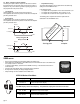
CDTX-90-3 Calibrate Menu Display (Factory settings shown) Cell Constant: Standard > Cell: Standard 1 > > Cond Units: uS > > Set: Temperature > > Loop1 Source: Cond > Loop1 Range: uS 0.0000 → 100.000 > Output Source: Cond > > Output1 Hys: 0.5000 uS > Output1 Rng: uS 10.0000 → 40.
CDTX-90-3 Options Menu Display (Factory settings shown) Contrast: 3 Cond Decimal: ****.* Description > > Set the decimal to the best resolution for your application. The display will automatically scale down to this restriction. Select *****., ****.*, ***.** **.*** or *.**** > OFF provides the most instantaneous response to process changes. Select LOW (4 sec) or HIGH (8 sec) averaging if your process experiences frequent or extreme fluctuations. Averaging Off Loop1 Adjust: 4.
Calibration Procedure 1. Requirements The CDTX-90 Transmitter is factory calibrated using simulated input signals. System calibration will reduce errors caused by sensor wire lengths longer than the standard 15 ft. length. Wire lengths of 100 feet are acceptable; cable shield must be maintained through cable splice. Calibration may be done by known solution value (A), or by resistance simulation (B).
Parts Per Million (PPM) Factor This feature is only applicable when PPM display units are selected. The programmable PPM Factor is adjustable from 0.01 to 3.00 (factory default = 2.00). Determine the best PPM Factor for a process solution by calculating the solution's conductivity (µS) and the percent of total dissolved solids (PPM).
Notes page 18
WARRANTY/DISCLAIMER OMEGA ENGINEERING, INC. warrants this unit to be free of defects in materials and workmanship for a period of 13 months from date of purchase. OMEGA’s WARRANTY adds an additional one (1) month grace period to the normal one (1) year product warranty to cover handling and shipping time. This ensures that OMEGA’s customers receive maximum coverage on each product. If the unit malfunctions, it must be returned to the factory for evaluation.
Where Do I Find Everything I Need for Process Measurement and Control? OMEGA…Of Course! Shop online at www.omega.