
Products, Inc Thermostat User Manual

11
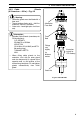
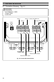
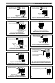
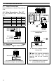
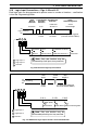
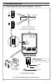
4 ELECTRICAL INSTALLATION…
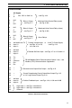
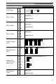
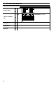
Table 4.1 Electrical Connections
Terminal Number
1
2
3 N/O
4 C
5 N/C
6 N/O
7 C
8 N/C
9 N/O
10 C
11 N/C
12
13
14
15
16
17
18 Tx+
19 Tx–
20 Common
21 Rx+
22 Rx–
23 +
24 –
25 +
26 –
27 3rd lead
28 Input 3+
29 Input 3–
30
31
32
3rd lead/2-wire TX
Input 1+
Input 1–
3rd lead
Input 2+
Input 2–
Retransmission Output/Cool Output – see Fig. 4.15
Process Variable Input or 2-wire Tx Power Supply
– see Figs. 4.7 to 4.9, – see Fig. 4.13
4.12 and 4.14
Remote Set Point Input – see Figs. 4.7 to 4.12 and 4.14
Relay 1 Output Motorized Valve Control Relay (open)
– see Fig. 4.17 – see Fig. 4.19A
Relay 2 Output Motorized Valve Control Relay (close)
– see Fig. 4.17 – see Fig. 4.19A
Relay 3 Output
– see Fig. 4.17
AC Supply
L
N
– see Fig. 4.22
Alarm Relays
Position Feedback Input – see Figs. 4.18 , 4.19A and 4.19B
Logic Input 1 – see Figs. 4.20 and 4.21
Logic Input 2 – see Figs. 4.20 and 4.21
Common
RS 485 Modbus Serial Communications Option 1 only – see
Modbus (RTU) Communications Supplement
Current Proportioning Control Output/Heat Output Fig. 4.15
or 12V Logic Control Output Fig. 4.16
24V, 115V or 230V a.c.