
user guide sensor CNiS8, CNiS8C, CNiS8DH, CNiS8DV, CNiS16, CNiS16D, CNiS32
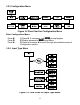


Determine
IN!1
and
IN!2
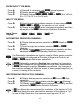
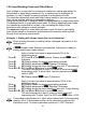
Input Range and Resolution. For our transducer select
0 ~ 100 mV range and LOW resolution (10 µV)
IN!1
= 0 (mV) X 100 (cts/mV) x 1.0 = 0
IN!2
= 30 (mV) X 100 (cts/mV) x 1.0 = 3000
2.
Determine correct values for Display Reading
(
RD!1
and
RD!2
)
. In most cases,
RD!1
and
RD!2
are equal to the minimum and the maximum of the transducer
output range.
RD!1
= 0000
RD!2
= 100.0
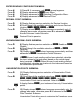
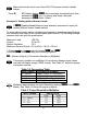
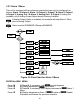
3. Scaling the controller.
Press
d
28) Press
d
at the
IN.RD
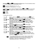
prompt. Display shows
IN!1
Input 1
Submenu.
Press
d
29) Display shows last stored Input 1 value with 1
st
digit flashing.
Press
b
&
c
30) Use
b
and
c
buttons to enter
IN!1
value (0000).
Press
d
31) Display advances to
RD!1
only, if a change was made,
otherwise press
a
to advance to
RD!1
Reading 1 Submenu.
Press
d
32)
Display shows last stored Reading 1 value with 1
st
digit
flashing.
Press
b
&
c
33)
Use
b
and
c
buttons to enter
RD!1
value (0000).
Press
d
34) Display
IN!2
Input 2
Submenu.
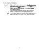
Press
d
35)
Display shows last stored Input 2 value with 1
st
digit flashing.
Press
b
&
c
36) Use
b
and
c
buttons to enter
IN!2
value (3000).
Press
d
37) Display advances to
RD!2
only, if a change was made,
otherwise press
a
to advance to
RD!2
Reading 2 Submenu.
Press
d
38)
Display shows last stored
Reading 2
value with 1
st
digit
flashing.
Press
b
&
c
39)
Use
b
and
c
buttons to enter
RD!2
value (1000).
Press
d
40) Display flashes
STRD
stored message momentarily and
then advances to
ALR1
only, if a change was made, otherwise
advances to
ALR1
Alarm 1 Menu.
This scaling method based on 2 input values entered with 2
corresponding reading. Up to 10 linearization points can be
selected to customize the transducer curve. To select
linearization points see “L.PNt” Submenu.
24