Omega.comTM http://www.omega.com e-mail: info@omega.
TABLE OF CONTENTS SPECIFICATIONS ................................................................................................................................................................ 3 DESCRIPTION ...................................................................................................................................................................... 4 DISPLAYING PARAMETERS..................................................................................................................
TABLE OF CONTENTS Electro-Mechanical Relay Option .................................................................................................................................... 20 Figure 2. Electro-mechanical Relays Hookup Example ............................................................................................... 20 FIG- 3. CONNECTIONS & REAR VIEW OF INSTRUMENT ........................................................................................ 21 POWER.................................
SPECIFICATIONS (Typical @ 25C and rated supply voltage unless otherwise specified) STANDARD INPUTS * 4-20ma 10-50ma 0-5Vdc 0-10Vdc * Thermocouple inputs: J,K,T,E,R,S,B * Cold junction compensation error: +/- 1C (10C to 40C) * Open input indication: HELP displayed * Temperature displayable in Degrees C or F * Non standard inputs available --- consult factory. ANALOG TO DIGITAL CONVERSION * 4-1/2 Digit (20,000) Count) A/D Converter * Dual slope integrating converter with 7 conversions /sec. (typical) rate.
NOTE DPS3104 and DPS3204 are four channel units. Therefore, any reference to channel numbers with respect to these models is for channels 1 through 4 only. DPS3100 (DPS3107) and DPS3200 (DPS3207) are seven channel units, and therefore, any reference to channel numbers for these models is for channels 1 through 7. DESCRIPTION DPS3000 Series instruments are multi-channel scanners that pack a number of functions into one unit.
DISPLAYING PARAMETERS DPS3000 Series keeps track of various parameters and these may be displayed by pushing appropriate keys on the front panel.
setpoint, difference between any two selected channels or just run as a timer. In the timer mode the unit keeps track of process run time with crystal controlled accuracy. Elapsed Time display format is 'HH.MM.SS' for hours, minutes, and seconds. The desired display mode is selected during SYS SETUP ---- (for details refer to the SYS CONFIGURATION section). Table 2. Display Modes MODE FUNCTION PERFORMED 1) Elapsed time Unit displays elapsed time since power up or last time reset.
Display time for each channel is programmable from 1-999 seconds (16.65 min.). This is useful for adjusting display time to a rate which is consistent with the type of process being monitored. Scan time for each channel is independent of display time. This permits programming long display times without losing track of the process on other channels. The display can also be put in a hold mode by pushing the SCN/HLD key.
a) The first one is a momentary display in which the deviation is indicated for a short time. Following this brief display time, the unit reverts to its normal mode of operation (scanning, differential, timer etc.). To achieve this, first select the channel whose setpoint deviation is desired. This is done by pushing the CH. SEL key. Next, push the RATE key twice. The first push displays the rate/minute value. The second push will display the deviation value.
Once the correct pass-code has been entered, the display shows 'SYS CH', with 'CH' blinking. At this point the operator may choose between making channel settings (CH), or system settings (SYS). Use ^v key to toggle between CH and SYS modes. When the desired mode is blinking, press SETUP key to begin setup of parameters for that mode.
CHANNEL CONFIGURATION After entering correct pass-code and selecting the blinking 'CH' (ref. SETUP section), the display shows 'SLCt CH' (for "Select Channel"). Use ^v key to display the desired channel. Selected channel will be displayed in the format 'CHANEL x' (where x=channel#). Once the desired channel # is displayed, push SETUP key to go on to setup parameters for the displayed channel #.
key and then pushing it again will decrement the value (^v key works as a toggle -- alternating between increment and decrement). To change the next digit first push the key. This will advance the flashing to the following digit. Use ^v key to change the value. After the desired High Scale setting is displayed, push SETUP key to enter that setting and go to setup Low Scale. Setup For Low Scale After setting a channel's High Scale, the next parameter to be set is Low Scale.
SETPOINT value. Once the desired SETPOINT value is displayed, push SETUP key to enter that value and go on to setup channel 1's operational mode. Setup for Universal Relay (Channel 1 Relay) Channel 1 relay can be configured to work as a universal relay or as Channel 1 relay only. In universal mode, this relay gets activated when ever any channel on the unit goes into alarm condition. In channel 1 mode, this output activates only if process reading on channel 1 exceeds channel 1's programmed limit value.
Setup For Engineering Units After setting a channel's relay for NORMALLY OPEN/CLOSED operation, the next parameter to be set are the 3 letters that follow the process value in the display. These 3 letters represent the measurement units for that particular channel. Any desired combination of the following letters may be programmed: A,B,C,D,E,F,G,H,I,J,L,N,O,P,Q,R,S,T,U,Y The letter selection goes up to 'Y' and down to 'A' and from 'A' down to ' - ' sign.
Example #2: Use of the LOW SCALE Parameter Setup for a 4-20ma transducer signal corresponding to 500-2000 degrees Fahrenheit temperature i.e. 500 degrees at 4ma and 2000 degrees at 20ma (one degree resolution): DECIMAL POINT HIGH SCALE LOW SCALE OFFSET TARE = 9999 = 2000 = 500 = 4.00 = 0.000 Example #3: Use of the TARE Parameter Setup for a 0-5Vdc transducer signal corresponding to 0-10.00 pounds of material being packaged in a box weighing 0.50 pounds with display reading in 0.01 lb. increments.
Setup For Relay Latch/Non-Latch After setting DISPLAY TIME, the next parameter determines whether the output relays will operate in a Latched or NonLatched mode. Relay Latched Mode: In this mode the relay is activated when its LIMIT value is exceeded and stays activated until the operator manually resets the relay. To manually reset a channel relay, use CH. SEL key to step to the desired channel number, and while keeping the CH. SEL key pressed, simultaneously press the RESET key.
desired value is displayed, push SETUP key to enter that value and go to the next step. Voltage Range Setup (for millivolt inputs) For Millivolt input units, the display first shows 'HV rnGE' (for "High Voltage Range"). After the High Voltage range is set, the display shows 'LV rnGE' (for "Low Voltage Range"). Enter values for respective inputs. Current Range Setup After VOLTAGE range has been set, the CURRENT range may be set.
PEAKS A very useful function of DPS3000 is tracking the highest (peak) and the lowest (valley ) point attained by each channel. This is particularly helpful if an operation is not being constantly watched or is left unattended (e.g. overnight). Since high and low points for each channel are monitored and stored separately, the history of changes at various points in the process can be obtained. This can be useful for quality control or for finding properties of a certain process.
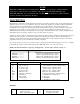
DPS3207 7 Channel Unit DPS3204 4 Channel Unit ENTER PASSCODE -- 3254 ‘SYS’ Flashing SYS CH ‘CH’ Flashing SELECT CHANNEL DISPLAY OPTION (Select one) ELAPSED TIME SCAN HIGH CHANNEL LOW CHANNEL DISPLAY DEVN. CHANNEL DIFF. IP TYPE -TC Option R,S or B Option -RTD Option -TH Option VOLTAGE CURRENT THERMISTOR DISPLAY TIME -P Option LO VOLTAGE HI VOLTAGE CURRENT VOLTAGE CURRENT RTD 385 RTD 392 VOLTAGE or CURRENT CHS. VOLTAGE CURRENT ‘R’ T/C ‘S’ T/C ‘B’ T/C VOLTAGE CURRENT ‘J’ T/C CR.
DPS3107 7 Channel Unit DPS3104 4 Channel Unit ENTER PASSCODE -- 3254 ‘SYS’ Flashing SYS CH ‘CH’ Flashing SELECT CHANNEL DISPLAY OPTION (Select one) ELAPSED TIME SCAN HIGH CHANNEL LOW CHANNEL DISPLAY DEVN. CHANNEL DIFF. -TH Option THERMISTOR DISPLAY TIME IP TYPE MV, V or C Option (Not Selectable) LO VOLTAGE VOLTAGE CURRENT -RTD Option RTD 385 RTD 392 VOLTAGE or CURRENT CHS. R,S or B Option (Not Selectable) ‘R’ T/C ‘S’ T/C ‘B’ T/C -TC Option ‘J’ T/C CR.AL T/C (K) ‘T’ T/C ‘E’ T/C TEMPERATURE CHS.
RATE DPS3000 series tracks the rate of process change/minute for each channel. This rate is displayed by first pushing the CH. SEL key to select the channel whose rate is desired. Once the channel has been selected, push rate key. The display will briefly read 'cx-rate' (x=channel #), and then the monitored rate for that channel. LIMITS DPS3000 series units support limit alarms on all the channels. These limits can be programmed over the entire range of selected thermocouple or scale.
NOTE: LOOK UNDER SPECIFICATIONS FOR THE RATING ON RELAYS AND OPEN COLLECTOR OUTPUTS. UNDER NO CONDITION SHOULD THE RELAYS AND OPEN COLLECTOR OUTPUTS BE OPERATED BEYOND THEIR RATED CAPACITY. DOING SO CAN DAMAGE THE UNIT PERMANENTLY. The status of the relays for all the channels is indicated on the front panel by a row of LEDs. Whenever the relay is energized, its respective LED is turned on. FIG- 3.
OUTPUT CONNECTOR PIN ASSIGNMENT 14 13 12 11 10 9 8 7 6 5 4 3 2 1 - + - + - + - + - + - + - + Table 1.
TROUBLE SHOOTING If the meter locks on a particular display, unplug and plug in again to unlock the display. A total reset defaults all scaling values to zero. To perform this reset, re-apply power with RESET key pressed in. Factory Channel settings: To obtain factory preset values simply re-apply power with ^v key pressed in. Factory settings are as follows: MODEL NO. MODEL NO. MODEL NO. CHANNEL NOS.
MOUNTING 3.70” (94mm) 0.15” dia. (3.81mm) 1.77” (45mm) 4.05” (102.87mm) Figure - 4. Panel Cutout and mounting hole dimensions 1. 2. 3. 4. Cut out Panel and mounting hole dimensions as shown in the figure 8. Remove the nuts from the mounting screws on the Panel Meter. Insert panel meter into the hole until it is flush with the panel. Install the nuts and tighten them till the unit is held firmly against the panel. 1. Remove nuts and insert Panel Meter & screws in mounting holes in panel cutout 2.
WARRANTY For Warranty information, check Omega’s web site at http://www.omega.
Page 26
Page 27
Page 28