MADE IN USA UserÕs Guide ® http://www.omega.com e-mail: info@omega.
OMEGAnet On-Line Service SM http://www.omega.com Internet e-mail info@omega.com Servicing North America: USA: ISO 9001 Certified Canada: One Omega Drive, P.O. Box 4047 Stamford, CT 06907-0047 TEL: (203) 359-1660 e-mail: info@omega.com 976 Bergar Laval (Quebec) H7L 5A1 TEL: (514) 856-6928 e-mail: info@omega.
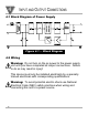
CONTENTS 1. 2. 3. 4. 5. 6. 7. General Information and Features Safety Considerations Installation and Removal 3.1 Installation Clearance 3.2 Mounting on DIN Rail 3.3 Removal of Unit Input and Output Connections 4.1 Block Diagram 4.2 Wiring for 115 Vac - Single Phase 4.
1 GENERAL INFORMATION AND FEATURES The compact DRN power supplies are designed to supply well-regulated 24 volt DC power to sensors, signal conditioners, data acquisition systems and high level logic equipment.
SAFETY CONSIDERATIONS 2 This device is marked with the international Caution symbol. It is important to read this manual before installing or commissioning this device as it contains important information relating to Safety and EMC (Electromagnetic Compatibility). Unpacking & Inspection Unpack the instrument and inspect for obvious shipping damage. Do not attempt to operate the unit if damage is found. This instrument is a DIN rail mount device.
3 INSTALLATION AND REMOVAL Warning! If a rail assembly is to be transported, then disconnection, dismounting and separate packing of the power supply is recommended. For units that must be shipped installed on the rail, additional bracing to resist transportation shocks is recommended. Do not attempt to install or connect to the power supply when the mains are energized.
INSTALLATION AND REMOVAL 3 3.1 Installation Clearance Ensure that there is enough room for mounting the power supply unit. There should be a minimum of 1" [25mm] spacing to allow sufficient air circulation for proper cooling. 1" 1" 24V-Bus Signal Conditioner Modules Power Supply Figure 3.
3 INSTALLATION AND REMOVAL 3.2 Mounting on DIN Rail To install unit onto DIN Rail 1. Tilt unit position mounting guide onto DIN Rail, as shown. 2. Push unit towards DIN Rail and it will snap into place. 1. Tilt 35mm Rail 2. •Push to • Snap on Mounting Guide Figure 3.2 Ñ Mounting on 35mm DIN Rail 32mm Rail Figure 3.
INSTALLATION AND REMOVAL 3 3.3 Removal of Unit The mounting guide can remain on DIN Rail and Power Supply can be removed. 1. While holding mounting guide, push unit upwards and unit will detach from mounting guide. 35mm Rail Push Up Hold Guide Figure 3.4 Ñ Removal of Unit CASE Mounting Guide 35mm (SHOWN) or 32mm DIN RAIL TAB MUST BE LOCATED AT BOTTOM. Figure 3.
4 INPUT AND OUTPUT CONNECTIONS 4.1 Block Diagram of Power Supply Figure 4.1 Ñ Block Diagram 4.2 Wiring Warning: Do not turn on the ac power to the power supply unit until you have completed all output connections. Failure to do so may result in injury! This device must only be installed electrically by a specially trained electrician with corresponding qualifications.
4 INPUT AND OUTPUT CONNECTIONS 4.2 Wiring (Continued) 115Vac - Single phase power wiring Line N e ut ral Switch Earth FUSE Input Power USE AWG 12-26 WIRE * •USE A SWITCH TO APPLY • • • • +24V POWER TO THE LOAD, IF THE CAPACITANCE OF THE LOAD WILL DRAW MORE THAN 7 AMPS AT TURN ON. Output Voltage (for shielded wire connections, if necessary) * Switch Earth Return +24 V To Signal Conditioner Modules Figure 4.
4 INPUT AND OUTPUT CONNECTIONS 4.3 Wiring (Continued) 230Vac - Two phase power wiring L1 L2 FUSE 1 Switch Earth FUSE 2 Earth * •USE A SWITCH TO APPLY • • • • +24V POWER TO THE LOAD, IF THE CAPACITANCE OF THE LOAD WILL DRAW MORE THAN 7 AMPS AT TURN ON. Output Voltage (for shielded wire connections, if necessary) * Switch Earth Return +24 V To Signal Conditioner Modules Figure 4.
SPECIFICATIONS 5 INPUT POWER Input Voltage: Frequency: Current: 115 - 240Vac ±10% 50/60 Hz 0.400A @ 103Vac 0.190A @ 265Vac Overvoltage Protection: 275 Volt Varistor Overcurrent Protection: Fuse TR-5 800mA Time-lag / IEC 127-3 Input Wattage: 26 Watts OUTPUT POWER Output Voltage: Output Wattage: 24Vdc ±2% @ 850mA (Resistive Load) 20 Watts* * For higher output wattage greater than 20 watts follow the chart on section 7, Figure 6.2.
5 SPECIFICATIONS GENERAL Operating Temperature: 23¡ to 122¡F(-5¡ to 50¡C) Storage Temperature: -40¡ to 176¡F(-40¡ to 80¡C) Mounting: 32 and 35mm DIN Rail Size: Height: 3.00" Width: 0.9" Depth: 3.67" Weight: 0.3 lbs. (0.
DIMENSIONS 6 0.9" (23mm) 3.00" (76mm) 3.
7 INPUT AC VOLTAGE / POWER OUTPUT AC INPUT CURRENT @ 100VAC INPUT OUTPUT POWER AC CURRENT 20W 21W 22W 23W 24W 338mA 355mA 373mA 392mA 412mA MAXIMUM POWER OUTPUT 24W 120V 23W 22W 21W 265V 115V INPUT AC VOLTAGE 110V 105V 20W 100V -5¼C 30¼C 35¼C 40¼C 45¼C 50¼C 25¼C AMBIENT TEMPERATURE ¼C Example: If ambient is 50¼C, maximum wattage is 21W max. for 120-265Vac. If unit is operated at 21W at an input voltage of 100V, the maximum ambient temperature allowed is 40¼C. Figure 6.
MADE IN USA WARRANTY/DISCLAIMER OMEGA ENGINEERING, INC. warrants this unit to be free of defects in materials and workmanship for a period of 13 months from date of purchase. OMEGA Warranty adds an additional one (1) month grace period to the normal one (1) year product warranty to cover handling and shipping time. This ensures that OMEGAÕs customers receive maximum coverage on each product. If the unit should malfunction, it must be returned to the factory for evaluation.
Where Do I Find Everything I Need for Process Measurement and Control? OMEGAÉOf Course! TEMPERATURE M U Thermocouple, RTD & Thermistor Probes, Connectors, Panels & Assemblies M U Wire: Thermocouple, RTD & Thermistor M U Calibrators & Ice Point References M U Recorders, Controllers & Process Monitors M U Infrared Pyrometers PRESSURE, STRAIN AND FORCE M U M U M U M U Transducers & Strain Gauges Load Cells & Pressure Gauges Displacement Transducers Instrumentation & Accessories FLOW/LEVEL M U M U M U M U R