User’s Guide Shop online at www.omega.com e-mail: info@omega.
Where Do I Find Everything I Need for Process Measurement and Control? OMEGA…Of Course! Shop online at www.omega.
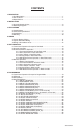
CONTENTS 1. DESCRIPTION 1.1 Unit Description ...............................................................................................1 1.2 Unit Features ...................................................................................................1 1.3 Specifications ..................................................................................................2 2. INSTALLATION 2.1 General Mounting Hints ...................................................................................6 2.
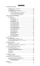
CONTENTS 7. PRINCIPLE OF OPERATION 7.1 General ..........................................................................................................38 7.2 Orifice Flowmeter Considerations .................................................................38 7.3 Flow Equations ..............................................................................................38 7.4 Calculating the Expansion Factor ..................................................................41 7.
FC-21 Flow Computer Unit Description 1. Description 1.1 Unit Description: The FC-21 Flow Computer satisfies the instrument requirements for a variety of flowmeter types in liquid applications. Multiple flow equations and instrument functions are available in a single unit with many advanced features. The alphanumeric display shows measured and calculated parameters in easy to understand format. Single key direct access to measurements and display scrolling is supported.
FC-21 Flow Computer 1.3 Specifications: Specifications: Environmental Indoor Use Altitude up to 2000m Operating Temperature: 0°C to +50°C (-20°C to 55°C optional) Storage Temperature: -40°C to +85 C Maximum Relative Humidity : 80% for temperatures up to 31°C decreasing linearly to 50% RH at 40°C Mains supply voltage fluctuations not to exceed ±10% of the nominal voltage Transient overvoltage according to INSTALLATION CATEGORY II (see UL 3101-1 Annex J) POLLUTION DEGREE 2 in accordance with IEC 664 (see 3.
FC-21 Flow Computer Relay Outputs The relay outputs are menu assignable to (Individually for each relay) Low Rate Alarm, Hi Rate Alarm, Prewarn Alarm, Preset Alarm, Pulse Output (pulse options) or General purpose warning (security). Operating Mode The Flow Computer can be thought of as making a series of measurements of flow, temperature/ density sensors and then performing calculations to arrive at a result(s) which is then updated periodically on the display.
FC-21 Flow Computer Setup Mode Maintenance Mode: The setup mode is password protected by means of The Maintenance Mode of the FC-21 is the Test a numeric lock out code established by the user. In and Calibration Mode for the device. This mode addition, a secret, manufacturers numeric unlock provides a number of specialized utilities required entry sequence is available. for factory calibration, instrument checkout on startup, and periodic calibration documentation.
FC-21 Flow Computer Operation of Serial Communication Port with Printers FC-21’s RS-232 channel supports a number of operating modes. One of these modes is intended to support operation with a printer in metering applications requiring transaction printing, data logging and/or printing of calibration and maintenance reports. Operation of Serial Port with Modems (optional) The FC-21 RS-232 channel supports a number of operating modes.
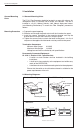
FC-21 Flow Computer 2. Installation General Mounting Hints 2.1 General Mounting Hints: The FC-21 Flow Computer should be located in an area with a clean, dry atmosphere which is relatively free of shock and vibration. The unit is installed in a 5.43" (138mm) wide by 2.68" (68mm) high panel cutout. (see Mounting Dimensions) To mount the Flow Computer, proceed as follows: Mounting Procedure a. Prepare the panel opening. b. Slide the unit through the panel cutout until the it touches the panel. c.
FC-21 Flow Computer 3. Applications Liquid Volume 3.1 Liquid Volume Measurements: A flowmeter measures the actual volume in a liquid line. A temperature sensor can also be installed to correct for liquid thermal expansion (see 3.2 Corrected Volume). Calculations: • For Flowmeters with Pulse Outputs, Volume flow is calculated using the flowmeter frequency output and the user entered K-Factor.
FC-21 Flow Computer Corrected Liquid Volume 3.2 Corrected Liquid Volume Measurements: A flowmeter measures the actual volume in a liquid line. A temperature sensor is installed to correct for liquid thermal expansion. Calculations: • Corrected Volume is calculated using the flow and temperature inputs as well as the thermal expansion coefficient stored in the flow computer. Use the "SET FLUID PROPERTIES" submenu to define reference temperature and density values for standard conditions.
FC-21 Flow Computer Liquid Mass 3.3 Liquid Mass Measurements: Actual volume is measured by the flow element (DP transmitter, Flowmeter). Temperature is measured by the temperature transmitter. A density transmitter can be used for direct density measurements.
FC-21 Flow Computer Batching 3.4 Batching Measurements: A flowmeter measures the actual volume in a liquid line. A temperature sensor can also be installed to correct for liquid thermal expansion (see 3.2 Corrected Volume). Calculations: • For Flowmeters with Pulse Outputs, Volume flow is calculated using the flowmeter frequency output and the user entered K-Factor. • For Flowmeters with Analog Transmitters, Volume flow is calculated using the measured flowmeter signal and the user entered scale settings.
FC-21 Flow Computer 4 WIRING Batcher Wiring 4.
FC-21 Flow Computer 4.
FC-21 Flow Computer 5. UNIT OPERATION 5.1 Front Panel Operation Concept for Run Mode The FC-21 is fully programmable through the front panel. Please review the following usage summary before attempting to use the instrument. TOTAL 1 RATE 2 PRE 1 3 TEMP 4 PRINT 5 GRAND 6 SCROLL 7 PRE 2 8 DENS 9 TIME START STOP 0 – CLEAR MENU HELP • ENTER How To Use On-Line Help HELP On-line help is provided to assist the operator in using this product.
FC-21 Flow Computer General Operation 5.2 General Operation The unit can display: Rate, Total, Grand Total, Temperature, Density, Presets and Time of Day. The Temperature and/or Density can be displayed even if you are using the Volumetric Flow Equation (a Temperature or Density sensor must be installed). The unit can perform Mass or Corrected Volume equations using a temperature or density sensor (these equations can be computed without Temp/Dens sensors by using user defined default values).
FC-21 Flow Computer RS-232 Serial Port (Rate/Total mode) 5.3.5 RS-232 Serial Port Operation in Rate/Total mode The RS-232 serial port can be used for programming (using the Setup Disk) or for communicating to printers and computers in the Operating Mode (Run Mode). PC Communications: The Setup Disk also allows the user to query the unit for operating status such as Flow Rate, Flow Total, Temperature, Density, Presets, etc.
FC-21 Flow Computer 5.4 Batcher Operation The Batcher mode is used primarily to control batches. The main difference between the Batch mode and Rate/Total mode is the relay operation. The Batch mode allows the operator to "START" the unit via the front panel or remote input. Once started, the relays (RLY1 & RLY2) will energize and send power to a flow control device (i.e. solenoid valve or pump). The flow sensor will send a signal to the unit and total accumulation will begin.
FC-21 Flow Computer Slow Start Quantity The Slow Start Quantity is a function that allows an amount to be entered for a Slow Start up. This function requires two stage valve control. RLY 1 (slow flow) will energize for Slow Start and RLY 2 (fast flow) will energize after the Slow Start Quantity has been delivered. This helps reduce turbulence when filling an empty container. START, RESET/START and STOP, STOP/RESET When configuring the control inputs, Control Input1 can be set for START or RESET/START.
FC-21 Flow Computer RS-232 Serial Port (Batch mode) 5.4.6 RS-232 Serial Port Operation in Batcher mode The RS-232 serial port can be used for programming (using the Setup Disk) or for communicating to printers and computers in the Operating Mode (Run Mode). PC Communications: The Setup Disk also allows the user to query the unit for operating status such as Flow Rate, Flow Total, Temperature, Density, Presets, etc.
FC-21 Flow Computer 6. PROGRAMMING 6.1 Front Panel Operation Concept for Program Mode The FC-21 is fully programmable through the front panel. Please review the following usage summary before attempting to use the instrument. START STOP TOTAL 1 RATE 2 PRE 1 3 TEMP 4 GRAND 6 SCROLL 7 PRE 2 8 DENS 9 PRINT 5 TIME 0 – CLEAR MENU HELP • ENTER Setup Mode: How To Make Mode Changes MODE CHANGES Pressing the MENU key will offer selections of RUN, SETUP, TEST.
FC-21 Flow Computer 6.2 EZ Setup The EZ Setup routine is a quick and easy way to configure the unit for the most commonly used instrument functions. This setup assumes that you are measuring Volumetric Flow using a high level, DC Pulsing flow sensor. Entering the EZ Setup mode automatically sets many features. This may cause any previously programmed information to be lost or reset. For a complete customized configuration, see sections 6.3 and 6.4. Menus 6.2.
FC-21 Flow Computer 6.3 Setup Menus Menus Display 6.3.1 Top Level Setup Menu 6.3.2 Submenu Groups Notes SELECT OPERATE STATE Run Setup Test MENU START Select Setup to enter the instrument setup routine. ENTER SELECT EZ SETUP Refer to Page 20 for Details. STOP START INSTRUMENT TYPE Refer to Page 22 for Details. STOP START SELECT FLOW EQUATION Refer to Pages 22 for Details. STOP START SETUP INDICATORS Refer to Page 23 & 24 for Details.
FC-21 Flow Computer 6.4 Setup Sub-Menus Sub-menus 6.4.1 SELECT EZ SETUP Display Notes Refer to page 20 for EZ Setup routine. SELECT EZ SETUP Press the DOWN (stop) key to advance to Instrument Type. Press the UP (start) key to advance to Administrative Setup. STOP START Advance To INSTRUMENT TYPE 6.4.2 INSTRUMENT TYPE Press ENTER to enter Instrument Type submenus.
FC-21 Flow Computer Sub-menus 6.4.3 SELECT FLOW EQUATION Notes Display SELECT FLOW EQUATION Press ENTER to enter Select Flow Equation submenus. ENTER SELECT FLOW EQUATION Volume Mass Cor/Vol Press ENTER when desired flow equation is flashing. ENTER Advance To SETUP INDICATORS (Total) 6.4.
FC-21 Flow Computer Sub-menus 6.4.6 SETUP INDICATORS (Rate) Display Notes SETUP INDICATORS Total Dens Rate Temp Press ENTER when Rate is flashing to configure the Ratemeter Indicators ENTER RATE TIME BASE Sec Min Hour Select the desired Rate Time Base. Day ENTER RATE DESCRIPTOR RATE Enter the desired Descriptor for the Ratemeter. ENTER RATE DEC PLACES Select the desired Rate Decimal Place. 0 0-3 decimal places allowed. ENTER RATE AVG FILTER Enter desired Rate Averaging Filter.
FC-21 Flow Computer Sub-menus 6.4.8 SETUP FLOW INPUT (Pulse - Ain & PS (A=B)) Display Notes Press ENTER to begin setup of Flow Input. SETUP FLOW INPUT ENTER EXCITATION VOLTAGE 5v 12v 24v Select the desired Excitation Voltage. ENTER Press ENTER when Pulse is flashing to configure the flow input for Pulse signals.
FC-21 Flow Computer Submenus 6.4.9 SETUP FLOW INPUT (Pulse - Quadrature, Qx1 or Qx2) Display Notes Press ENTER to begin setup of Flow Input. SETUP FLOW INPUT ENTER Select the desired Excitation Voltage. EXCITATION VOLTAGE 5v 12v 24v ENTER Press ENTER when Pulse is flashing to configure the flow input for Pulse signals. FLOW INPUT TYPE Pulse Analog ENTER NOTE: Ain = Single Pulse PS(A=B) = Pulse Security Qx1 = Quadrature Qx2 = Quadrature x 2 Enter the desired Pulse type. See side note.
FC-21 Flow Computer Sub-menus Display Notes SETUP FLOW INPUTS 6.4.10 SETUP FLOW INPUT (Analog) Press ENTER to begin setup of the Flow Input. ENTER EXCITATION VOLTAGE 5v 12v 24v Select the desired Excitation Voltage. ENTER FLOW INPUT TYPE Pulse Analog Press ENTER when Analog is flashing to configure the flow input for Analog signals . ENTER ANALOG SIGNAL TYPE Voltage Current Choose Analog Signal Type.
FC-21 Flow Computer Sub-menus 6.4.11 SETUP AUX INPUT Display Notes SETUP AUX INPUT Press ENTER to begin setup of the Auxiliary Input. ENTER NOTE: When Density (Dens) is selected, The menu prompts will be very similar to the Temperature prompts. The menus will prompt the user for density values and density units. AUX INPUT TYPE None Dens Temp Select Temperature to set the Auxiliary Input for Temperature inputs. ENTER AUX SIGNAL TYPE Voltage Current RTD Choose Temperature Signal Type.
FC-21 Flow Computer Sub-menus 6.4.12 SET FLUID PROPERTIES Display Notes SET FLUID PROPERTIES Press ENTER at this prompt to Set Fluid Properties. ENTER Enter the Reference Density. This is used in the calculation of density when you have a REF. DENSITY ###### lbs/g temp transmitter and used for corrected flow calculation if you have a density transmitter. ENTER REF. TEMPERATURE ###### Enter the Reference Temperature. F ENTER Enter the proper Expansion Factor. EXPAN.
FC-21 Flow Computer Sub-menus 6.4.14 SETUP ANALOG OUTPUT Display Notes SETUP ANALOG OUTPUT Press ENTER when Analog is flashing to setup the Analog Output. ENTER Select the desired Analog Output Usage. ANALOG OUTPUT USAGE Rate Total Temp Dens ENTER ANALOG OUT FLOW TYPE Only if Rate selected & Flow EQ. = Mass, Cor/Vol Vol CVol/Mass Select the desired Analog Output Flow. ENTER ANALOG OUTPUT RANGE Select the desired current range for the Analog 4-20mA 0-20mA Output.
FC-21 Flow Computer Sub-menus 6.4.15 (Continued) SETUP RELAYS (Relay 3 & Relay 4) Display Notes SETUP RELAYS Rly1 Rly2 Rly3 Rly4 Select the desired Relay for setup. (Relays 3 & 4 Optional) ENTER NOTE: Settings for Relays 3 & 4 may be entered even if relays are not supplied. The settings will still trigger display alarms. RELAY 3 USAGE Rate Tot Aux Ovrn NA If Relay 3 Selected, Choose Rate, Total, Aux, Ovrn or NA.
FC-21 Flow Computer Sub-menus 6.4.16 SETUP CONTROL INPUTS (RATE/TOTAL) Display Notes SETUP CONTROL INPUTS Press Enter to begin setup of the Control Inputs. ENTER SETUP CONTROL INPUTS Input1 Input2 Input3 Select the desired Control Input for setup. ENTER CONTROL INPUT1 USAGE INHIBIT_TOTAL NA If Control Input 1 Selected, Select Inhibit Total or NA (Not Assigned). CONTROL INPUT2 USAGE RESET_TOTAL NA If Control Input 2 Selected, Select Reset Total or NA (Not Assigned).
FC-21 Flow Computer ENTER ENTER ENTER ENTER ENTER ENTER ENTER 33
FC-21 Flow Computer Sub-menus 6.4.20 SERIAL USAGE Display Notes SERIAL USAGE Press Enter to begin setup of the Serial Port. ENTER SERIAL HARDWARE RS232 RS485 ENTER DEVICE ID Select Serial Hardware type for standard port. (See SETUP NETWORK CARD for RS485 Modbus option) Select the Device ID. ## ENTER BAUD RATE 300 600 1200 Select the desired Baud Rate. BAUD RATE 2400 4800 9600 19200 (If selected) ENTER PARITY None Select the desired Parity.
FC-21 Flow Computer Sub-menus 6.4.20 SERIAL USAGE (continued) Display Notes CALL ON ERROR/ALARM No Yes Select "Yes" to have the unit perform a Call Out transmission upon error/alarm condition. ENTER NUMBER OF REDIALS 0 ENTER HANGUP IF 2MIN INACT No Yes Enter the number of redials to be performed on call out time if busy or no answer. (error/ alarm tries until connected) Select "Yes" to perform hangup if there is inactivity for more than 2 minutes. ENTER Advance To SETUP DATALOG/PRINT 6.4.
FC-21 Flow Computer Sub-menus 6.4.22 SETUP DATALOG/PRINT (Select_list) STOP START List Items: TOTAL RATE PRE1 TEMP GRAND PRE2 DENS TIME Display Notes SET DATALOG/PRINT Press enter to begin Setup Datalog/Print routine. ENTER SET DATALOG/PRINT Config Select_list Press enter when Select_list is selected to setup print list. PRINT LIST ITEMS TOTAL YES Use Up and Down arrow keys to view list status. Press the Corresponding function key to the items that you wish to add or remove from the list.
FC-21 Flow Computer 6.4.24 SETUP NETWORK CARD (optional) SETUP NETWORK CARD Press Enter to setup Network Card ENTER SELECT NTW PROTOCOL ModbusRTU Select desired Network Protocol. ENTER NETWORK DEVICE ID 1 Enter the device address on network (00255). ENTER BAUD RATE 2400 4800 9600 19200 Select the desired Baud Rate. ENTER PARITY None Select the desired Parity.
FC-21 Flow Computer 7. Principle Of Operation General Operation 7.1 General: The FC-21 Flow Computer uses several internal calculations to compute the compensated flow based on specific data input. Several computations are performed to arrive at the uncompensated flow, temperature, density and viscosity. This information is then used to compute the Corrected Volume Flow or Mass Flow. Orifice Flowmeter Considerations 7.
FC-21 Flow Computer 7.3 Flow Equations: (Continued) Flow Equations Input Viscosity Computation: † centistokes = (A exp ) B (Deg F + 459.
FC-21 Flow Computer 7.3 Flow Equations: (Continued) Flow Equations The above information was obtained from "Flow Measurement Engineering Handbook, 3rd Edition" by Richard W Miller.
FC-21 Flow Computer 7.4 Calculating the Expansion Factor Calculating Expansion Factor The liquid density is a function of the flowing temperature for many fluids. This unit solves an equation which represents this physical property of the fluid. The information which the unit uses to describe the fluid is entered by the user in the following variables: Reference Temperature, Reference Density, Expansion Factor.
FC-21 Flow Computer 7.5 Computation of Viscosity Coef. A and B Computation of Viscosity Coef. A & B The flow computer solves an equation which computes the viscosity as a function of temperature. Two parameters must be entered for this calculation to be performed. These are the setup parameters Viscosity Coef. A and Viscosity Coef. B. Alternately, if your intended fluid is not listed, the Viscosity Coef. A and B can be derived from two known temperature/viscosity pairs.
FC-21 Flow Computer 7.6 Linearization Table Linearization Table General Information 7.6.1 Linearization Table General Information The Linearization Table is used when the flow input device gives a nonlinear input signal. The unit uses up to 16 different points, as entered by the operator, to form a curve for linearizing the input signal. Notes: 1) A minimum of three points must be set up.
FC-21 Flow Computer 8. Test, Service and Maintenance 8.1 Test Menus Menus Display 8.1.1 TOP LEVEL TEST MENUS Notes Select Test to enter the instrument test & calibration routine. SELECT OPERATE STATE Run Setup Test NOTE: Supervisor (Service) password required to gain access to this mode. ENTER START Refer to Page 40 for Details. Audit Trail STOP START Refer to Page 40 for Details. Error history STOP START Refer to Page 40 for Details. Print System Setup STOP START Refer to Page 41 Details.
FC-21 Flow Computer 8.2 Test Sub-Menus Sub-menus 8.2.1 Audit Trail Submenu Group Display Notes Audit Trail Press Enter to view the audit trail information. ENTER Audit Trail nnnnn hh:mm:ss mm/dd/yy MENU 8.2.2 Error History Submenu Group Audit Trail Press Menu to get back to audit trail top-level menu. Error history Press Enter to view error history. NOTE: Press Print Key to print Error History. Printout will include time/date of each errors first occurrence.
FC-21 Flow Computer Sub-menus 8.2.4 Keypad test Submenu Group Display Notes Keypad test Press Enter to enter keypad test ENTER Press the various keys and the display will show the key that was pressed. Press Menu to exit the test Keypad test Key pressed—> ENTER MENU 8.2.5 Display test Submenu Group Keypad test Press Menu to get back to Keypad test toplevel menu. Display test Press Enter to enter display test.
FC-21 Flow Computer ALL UNITS ARE CALIBRATED AT THE FACTORY PRIOR TO SHIPMENT CAUTION: This unit must be calibrated using precision and calibrated equipment. Equipment needed is as follows: Frequency Generator, Digital Multimeter, Precision Current/Voltage Source, Oscilloscope, Frequency Counter. Sub-menus Display Notes Calibrate Press Enter to begin the calibration routine. Calibration Submenu Group (Please note the caution above) ENTER 8.2.
FC-21 Flow Computer Sub-menus 8.2.8 Calibrate CH2 0mA Submenu Group Display Notes Calibrate ch2 0mA Iin=TB1-8 GND=TB1-4 To Calibrate: Connect Current Source (+) TB1-8, (-) TB1-4. Input 0mA and press Enter. ENTER Calibrate ch2 0mA 0 CALIBRATING —— This message is displayed during calibration. Calibrate ch2 0mA *** DONE *** This message is displayed when the 0mA calibration is finished. Calibrate ch2 0mA Iin=TB1-8 GND=TB1-4 The display will automatically return to the Calibrate CH2 0mA submenu.
FC-21 Flow Computer Sub-menus 8.2.10 Calibrate CH1 0V Submenu Group Display Notes Calibrate ch1 0V Vin=TB1-2 GND=TB1-4 To Calibrate: Connect Voltage Source (+) TB1-2, (-) TB1-4. Input 0V and press Enter. ENTER 8.2.11 Calibrate CH1 10V Submenu Group Calibrate ch1 0V 0 CALIBRATING —— This message is displayed during calibration. Calibrate ch1 0V *** DONE *** This message is displayed when the 0V calibration is finished.
FC-21 Flow Computer Sub-menus 8.2.12 Calibrate CH2 0V Submenu Group Display Notes Calibrate ch2 0V Vin=TB1-5 GND=TB1-4 To Calibrate: Connect Voltage Source (+) TB1-5, (-) TB1-4. Input 0V and press Enter. ENTER Calibrate ch2 0V 0 CALIBRATING —— This message is displayed during calibration. Calibrate ch2 0V *** DONE *** This message is displayed when the 0V calibration is finished. Calibrate ch2 0V Iin=TB1-5 GND=TB1-4 The display will automatically return to the Calibrate CH2 0V top-level menu.
FC-21 Flow Computer Sub-menus 8.2.15 Calibrate 4mA Out Submenu Group Display Calibrate + TB1-15 Notes 0mA out Connect ammeter to (+) TB1-15, (-) TB1-16. - TB1-16 Press enter. ENTER To trim 0mA output: Press CLEAR to enable editing and enter a small negative number (i.e. 0.100) to force a display reading, then clear and enter small quantity measured on your meter. Calibrate 0mA out Enter mA: 0.00000 ENTER Calibrate + TB1-15 0mA out The display will return to Calibrate 0mA out.
FC-21 Flow Computer Sub-menus 8.2.18 Pulse input test Submenu Group Display Notes Pulse input test Press Enter key to test the pulse input. ENTER 2.5V 10mV 100mV START STOP Pulse input test Trigger level 2.5V Use the Up/Down arrow keys to select the appropriate trigger level. ENTER 40Hz 3KHz 20kHz START STOP Pulse input test count speed 3kHz ENTER Pulse input test F1: 0 F2: 0 MENU 8.2.
FC-21 Flow Computer Sub-menus 8.2.21 Pulse out test Submenu Group Display Notes Press Enter key to test the pulse output. Pulse out test ENTER Pulse out test *0Hz 1Hz 10Hz 20Hz MENU 8.2.22 Relay test Submenu Group Pulse out test Press Menu key to return to Pulse out test top-level menu. Relay Test Press Enter to test the relays. ENTER Rly1 Rly2 Rly3 Rly4 Off Off Off Off MENU 8.2.
FC-21 Flow Computer Sub-menus 8.2.24 Battery Voltage test Submenu Group Display Notes Battery Voltage Test Press Enter key to view the battery voltage. ENTER Battery Voltage Test 3.312 Volts The display will show the battery voltage. Replace battery at 2.5 VDC or below. MENU 8.2.25 Data logger utility Submenu Group Battery Voltage Test Press Menu key to return to battery voltage test top-level menu. Data logger utility Press Enter to use data logger utility.
FC-21 Flow Computer 8.3 Internal Fuse Replacement Instructions: 1. Make sure you follow proper E.S.D. Precautions. All persons performing this replacement must follow proper grounding procedures. 2. Turn the power to the unit off. 3. Disconnect the two piece connector rear terminal block, leaving all connections in place. 4. Remove the unit from the panel. 5. Remove the four machine screws (see fig. 1) which hold the two sections of the case together. 6.
FC-21 Flow Computer 9. RS-232 Serial Port 9.1 RS-232 Port Description: The FC-21 has a general purpose RS-232 Port which may be used for any one of the following purposes: Transaction Printing Data Logging Remote Metering by Modem (optional) Computer Communication Link Configuration by Computer Print System Setup Print Calibration/Malfunction History 9.
FC-21 Flow Computer 10. RS-485 Serial Port (optional) 10.1 RS-485 Port Description: The FC-21 has a an optional general purpose RS-485 Port which may be used for any one of the following purposes: Accessing Process Parameters Rate, Temperatures, Density, Setpoints, Month, Day, Year, Hour, Minutes, Seconds, etc.
FC-21 Flow Computer 11. Flow Computer Setup Software The FC-21 setup program provides for configuring, monitoring and controlling a FC21 unit. Sample applications are stored in disk files. The setup program calls these Templates. You can store the setup from the program’s memory to either the FC-21 (Downloading the file) or to a disk file (Saving the file) for later usage. Similarly you can load the setup in program memory from either a disk file (Opening a file) or from the FC-21 unit (Uploading a file).
FC-21 Flow Computer 11.4 Using the Flow Computer Setup Software The setup software window consists of several menu “Tabs”. Each tab is organized into groups containing various configuration and/or monitoring functions. To view the tab windows, simply click on the tab. The previous tab window will be hidden as the new tab window is brought to the foreground. 11.5 File Tab The File Tab has three sections. Any of the options on this tab can also be accessed from the File submenu.
FC-21 Flow Computer 11.7 View Tab The View Tab screen allows for viewing selected group items on the PC in a similar format as shown on the unit display. Data from the following groups can be viewed in the List of Values section: Process Parameters (i.e. rate, temperature) Totalizers (i.e. total, grand total) The setup software assumes the current setup has been uploaded from the flow computer into the PC.
FC-21 Flow Computer 12. Glossary Of Terms Acknowledge & Clear Alarms Acknowledge is used to clear alarm relays and remove any visual alarm messages from the display. In the run mode, press the ENTER key or activate CONTROL INPUT 3 (if set for ACK) to momentarily clear alarms and alarm messages. Alarms will reassert themselves if alarm conditions are still present. Analog Output The analog signal (4-20mA) that is generated by the FC-21. It can correspond to the Rate, Total, Temperature or Density.
FC-21 Flow Computer 12. Glossary Of Terms (Continued) Flow Signal Timeout The Flow Signal Timeout allows the user to enter a timeout of 0 to 99 seconds. If a batch is “Filling” and zero flow persists for more than the user entered time then the batch will be aborted. This prevents over flows due to faulty flow sensors and/or wiring. Flow Equation A flow control expression or algorithm describing a mathematical equation to be solved by a flow computer in the desired application.
FC-21 Flow Computer 12. Glossary Of Terms (Continued) Mass Flow is inferred by the volumetric flow and density (or implied density) of a fluid. Maximum Batch Preset The Maximum Batch Preset allows the user to program the Maximum Batch value allowed to be entered by the operator. If an operator should try to program a batch higher then this value, the unit will not allow the value to be entered and will prompt the user with an error message saying that the Maximum Batch Preset has been exceeded.
FC-21 Flow Computer 12. Glossary Of Terms (Continued) following: 1) Prompts the user for only critical information. 2) Automatically sets specifications to common uses. After following the Quick Setup procedure, the unit will be operational to perform the basic measurement. The setup can be further customized using the setup menus. Quick Update % This feature is used to disable the rate averaging filter when a significant change in the flow rate occurs.
FC-21 Flow Computer 13. Diagnosis and Troubleshooting 13.1 Response of FC-21 on Error or Alarm: Error and warning indications which occur during operation are indicated in the RUN mode alternately with the measured values. The FC-21 Flow Computer has three types of error: TYPE OF ERROR DESCRIPTION Sensor/Process Alarms Errors detected due to sensor failure or process alarm conditions Self Test Errors Errors detected during self test.
FC-21 Flow Computer 13.2 Diagnosis Flow Chart and Troubleshooting All instruments undergo various stages of quality control during production. The last of these stages is a complete calibration carried out on state-of-the-art calibration rigs. A summary of possible causes is given below to help you identify faults. Is there an input power supply voltage across Terminals 23 and 24? No Yes Is the Display Backlight Visible? Check the connections according to the circuit diagrams. Check junction box fuses.
FC-21 Flow Computer 13.3 Error & Warning Messages: 13.3.1 Sensor/Process Alarms Error/Warning Message Cause Remedy TOTALIZER ROLLOVER Displayed when totalizer rolls over Acknowledge Rollover, Remedy not required AUX INPUT TOO LOW 4-20 mA Input current at aux input smaller than 3.
FC-21 Flow Computer 13.3 Error & Warning Messages: (Continued) 13.3.
SETUP AUX INPUT 69 DEVICE ID SERIAL HARDWARE SETUP DATALOG/ PRINT OPERATOR PASSWORD SELECT NETWORK PROTOCOL SERIAL USAGE SETUP DATALOG/PRINT ADMINISTRATIVE SETUP SETUP NETWORK CARD NETWORK DEVICE ID SUPERVISOR PASSWORD OUTPUT FORMAT CLOCK TYPE SETUP REAL TIME CLOCK SETUP REAL TIME CLOCK SETUP CONTROL INPUTS 1, 2, 3 SETUP CONTROL INPUTS CONTROL INPUT 1 USAGE RELAY USAGE SETUP RELAYS 1, 2, 3, 4 SETUP RELAYS BAUD RATE SOFTWARE VERSION PAGE LENGTH BAUD RATE SELECT CLOCK AM/PM CONTROL
WARRANTY/DISCLAIMER OMEGA ENGINEERING, INC. warrants this unit to be free of defects in materials and workmanship for a period of 13 months from date of purchase. OMEGA’s WARRANTY adds an additional one (1) month grace period to the normal one (1) year product warranty to cover handling and shipping time. This ensures that OMEGA’s customers receive maximum coverage on each product. If the unit malfunctions, it must be returned to the factory for evaluation.
OMEGAnet ® Online Service www.omega.com Internet e-mail info@omega.com Servicing North America: USA: ISO 9001 Certified Canada: One Omega Drive, P.O. Box 4047 Stamford CT 06907-0047 TEL: (203) 359-1660 e-mail: info@omega.com 976 Bergar Laval (Quebec) H7L 5A1 TEL: (514) 856-6928 e-mail: info@omega.