
Products, Inc Stud Sensor User Manual

SECTION 3.0
SENSOR PREPARATION
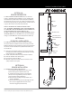
FIG. 2
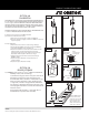
3.0 FREE CHLORINE SENSOR ASSEMBLY. The Free Chlorine
Sensor is shipped with the membrane cap pre-installed and
covered with a cap with water inside to keep the membrane
wet. Make sure to keep sensor cap, anode and cathode inside
the sensor body, away oily or greasy materials. Contact with oil
or grease will result in inaccurate measurements.
NOTE: IF SENSOR WILL BE STORED DRY OUT OF FLOW
CELL, SHAKE BODY DOWNWARD INTO A SINK TO REMOVE THE
FILL SOLUTION. TAKE THE MEMBRANE CAP AND IMMERSE IN A
CUP OF TAP WATER UNTILL READY TO REUSE. SEE
SECTION 9. REPLACE CAP AND ELECTROLYTE BEFORE INSTALL-
ING INTO FLOW CELL (see SECTION 10 for cap and electrolyte
change. See SECTION 5 for sensor installation into flow cell).
SECTION 4.0
FLOW CELL INSTALLATION
4.0 FLOW CELL. To obtain accurate Free Chlorine reading,
the Sensor must be installed into the Flow Cell to prevent air
bubbles formation on the membrane, proper spacing between
the sensor and the installation wall, and laminar flow across
the membrane.
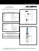
4.1. Using two 1/4” NPT Tube fittings, connect the FC72 Flow
Cell into your system, noting the inlet (bottom) and outlet
(side) orientation. (see FIGURE 2)
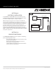
4.2. Install clamp with rubber backing as shown in FIG. 2A.
4.3 Drill 3/8" diameter hole on the panel.
4.4 Insert bolt as shown in FIG 2A
4.5 On back of panel attach lock washer and nut to secure
clamp and flow cell to panel.
PRODUCT INSTRUCTION SHEET
SECTION 5.0
SENSOR INSTALLATION
5.0 SENSOR INSTALLATION INTO FLOW CELL.
a. First install threaded fitting onto sensor body
(remove fitting if pre-installed in flow cell)
b. Install snap-ring into groove on sensor body
c. Next, slide o-ring onto body of sensor until it
reaches bottom of threaded fitting.
d. Thread sensor assembly into top of flow cell as
shown in FIGURE 2.
d. Turn on flow and verify the flow through the Flow
Cell is at least 0.2gpm (45 liters/hour and no
more than 0.6gpm (135 liters/hour).
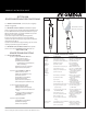
THREADED FITTING
O-RING
SNAP RING (INSTALLS
INTO PROBE GROOVE)
SNAP RING
GROOVE
BARBED TUBE
FITTING
BARBED TUBE
FITTING
FLOW CELL
SENSOR
FIG. 2A
FC72 Flow cell
Parts covered by this product instruction sheet include: FCLTX-100 Series
M4679/0708 page 2 of 6