
Products, Inc Stud Sensor User Manual
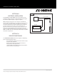
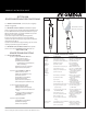

Power Supply
PLC, DVM,...
sensor red wire
sensor
black wire
FIG. 3
PRODUCT INSTRUCTION SHEET
6.0 ELECTRICAL INSTALLATION. The sensor produces an ap-
proximate output of 4 mA in air and 20mA at the top range of
free chlorine output (0-2ppm, 0-5ppm, 0-10ppm).
NOTE: The supply voltage to the Sensor must be 12-24 V DC with
minimum of 250 mA. Maximum load is 1 Watt. The sensor has 3 wires,
red (+) , black (-) and clear (shield). Twist together or solder black
and clear if instrument does not have separate ground. If a separate
ground is available such as for PLC’s connect clear (shield) to it.
Attach the red wire to the power supply positive terminal (+)and the
black wire to the PLC or DVM positive (+) terminal. Connect a wire
(customer supplied) from the power suppy negative (-) and the PLC or
DVM (-). See FIG 3. The Sensor will require several minutes to stabilize
after power is supplied to it.
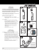
7.0 SENSOR CONDITIONING The sensor requires conditioning
prior to generating stable values.
a. For new Sensors, allow the Sensor to run for at least
4 hours before calibration.
b. If the Sensor will be un-powered for 2 hours or
more, run for 3 hours prior to use.
c. After membrane/electrolyte replacement, allow the
Sensor to run for at least 4 hours.
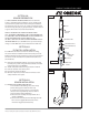
SECTION 6.0
ELECTRICAL INSTALLATION
SECTION 7.0
SENSOR CONDITIONING
Parts covered by this product instruction sheet include: FCLTX-100 Series
M4679/0708 page 3 of 6