User’s Guide Shop online at www.omega.com e-mail: info@omega.
OMEGAnet ® Online Service www.omega.com Internet e-mail info@omega.com Servicing North America: USA: ISO 9001 Certified Canada: One Omega Drive, Box 4047 Stamford CT 06907-0047 Tel: (203) 359-1660 e-mail: info@omega.com 976 Bergar Laval (Quebec) H7L 5A1 Tel: (514) 856-6928 e-mail: info@omega.
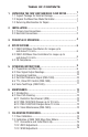
TABLE OF CONTENTS 1 1. UNPACKING THE FMA 1400/1500 MASS FLOW METER................ 1.1 Inspect Package for External Damage.........................................1 1 1.2 Unpack the Mass Flow Meter/Controller....................................... 1.3 Returning Merchandise for Repair...............................................1 2. INSTALLATION............................................................ 1 2.1 Primary Gas Connections............................................................1 2.
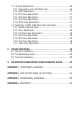
7.3 Linearity Adjustment...................................................................... 16 7.3.1 Connections and Initial Warm Up........................................... 16 7.3.2 ZERO Adjustment.................................................................17 7.3.3 25% Flow Adjustment............................................................. 17 7.3.4 50% Flow Adjustment............................................................ 17 7.3.5 75% Flow Adjustment.....................................
TRADEMARKS Buna7 is a registered trademark of DuPont Dow Elastometers. Kalrez7 is a registered trademark of DuPont Dow Elastomers. Neoprene7 is a registered trademark of DuPont. Omega®-is a registered trademark of Omega Engineering, Inc. VCR7 is a registered trademark of Crawford Fitting Co. Viton7 is a registered trademark of Dupont Dow Elastometers L.L.C.
1. UNPACKING THE FMA 1400/1500 MASS FLOW METER AND CONTROLLER 1.1 Inspect Package for External Damage Remove the Packing List and verify that you have received all equipment. If you have any questions about the shipment, please call the Omega7 Customer Service Department at 1-800-622-2378 or (203) 359-1660. Your FMA 1400/1500 Mass Flow Meter/Controller was carefully packed in a sturdy cardboard carton, with anti-static cushioning materials to withstand shipping shock.
It is also preferable to install the FMA 1400/1500 transducer in a stable environment, free of frequent and sudden temperature changes, high moisture, and drafts. Prior to connecting gas lines inspect all parts of the piping system including ferrules and fittings for dust or other contaminants. Be sure to observe the direction of gas flow as indicated by the arrow on the front of the meter when connecting the gas system to be monitored.
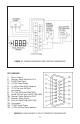
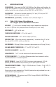
FIGURE 2-1, WIRING DIAGRAM FOR FMA 1400/1500 TRANSDUCERS PIN FUNCTION 1 2 3 4 5 6 7 8 9 10 11 12 13 14 15 Chassis Ground Common, Signal Ground For Pin 3 0-5 VDC Flow Signal +15 VDC Power Supply (-) 4-20 mA Flow Signal (optional) +7 VDC for Local Set Point (unassigned) TTL Valve Off Control (FMA 1400) Control Set Point Input 0 5 VDC (FMA 1400) Common, Signal Ground for Pin 9 Common, Power Supply Valve Test Point/Purge (FMA 1400) (unassigned) -15 VDC Power Supply (+) 4-20 mA Flow Signal (optional) FIGURE 2
Important notes: In general, "D" Connector numbering patterns are standardized. There are, however, some connectors with nonconforming patterns and the numbering sequence on your mating connector may or may not coincide with the numbering sequence shown in our pin configuration table above. It is imperative that you match the appropriate wires in accordance with the correct sequence regardless of the particular numbers displayed on your mating connector.
4. SPECIFICATIONS FLOW MEDIUM: Please note that FMA 1400/1500 Mass Flow Meters and Controllers for ranges up to and above 10 L/min are designed to work with clean gases only. Never try to meter or control flow rates of liquids with any FMA 1500's or FMA 1400's. CALIBRATIONS: Performed at standard conditions [14.7 psia (1.01 bars) and 70FF (21.1FC)] unless otherwise requested or stated. ENVIRONMENTAL (per IEC 664): Installation Level II; Pollution Degree II 4.
Omega7 makes no expressed or implied guarantees of corrosion resistance of mass flow meters as pertains to different flow media reacting with components of meters. It is the customers' sole responsibility to select the model suitable for a particular gas based on the fluid contacting (wetted) materials offered in the different models. INLET AND OUTLET CONNECTIONS: 1/4"compression fittings standard on ranges up to 50 L/min; 3/8” compression fittings standard on 60, 80, and 100 L/min ranges.
ATTITUDE SENSITIVITY: 1% shift for a 90 degree rotation from horizontal to vertical; standard calibration is in horizontal position. OUTPUT SIGNALS: Linear 0-5 VDC (2000 Ω minimum load impedance); 4-20 mA optional (50-500 Ω loop resistance); 20 mV peak to peak max noise. COMMAND SIGNAL: 0-5 VDC (200K Ω input impedance). TRANSDUCER INPUT POWER: FMA 1400 ranges up to 10 L/min: (15 sLit/min max) +15 +5% VDC, 80 mA max, 1.
FLOW RANGES TABLE I FMA 1500/1400 FOR RANGES UP TO 10 L/MIN LOW FLOW MASS FLOW METER/CONTROLLERS* CODE scc/min [N2] CODE std liters/min [N2] 02 0 to 10 14 0 to 1 04 0 to 20 16 0 to 2 06 0 to 50 18 0 to 5 08 0 to 100 20 0 to 10 10 0 to 200 12 0 to 500 TABLE II FMA 1500/1400 FOR RANGES ABOVE 10 L/MIN MEDIUM FLOW MASS FLOW METER/CONTROLLERS* CODE standard liters/min [N2] 23 15 24 20 26 30 27 40 28 50 TABLE III FMA 1500/1400 FOR RANGES ABOVE 10 L/MIN HIGH FLOW MASS FLOW METER
TABLE IV PRESSURE DROPS MODEL FMA 1500 FMA 1400 MAXIMUM PRESSURE DROP FLOW RATE [std liters/min] [mm H2O] [psid] [mbar] up to 10 25 0.04 2.5 15 63 0.09 6.4 20 300 0.44 30 30 800 1.18 81 40 1480 2.18 150 50 2200 3.23 223 60 3100 4.56 314 80 4422 6.50 448 100 up to 10 5500 8.08 557 720 1.06 75 15 2630 3.87 266 20 1360 2.00 138 30 2380 3.50 241 40 3740 5.50 379 50 5440 8.00 551 60 7480 11.00 758 80 10204 15.00 1034 100 12850 18.
During initial powering of the FMA 1400/1500 transducer, the flow output signal will be indicating a higher than usual output. This is indication that the FMA 1400/1500 transducer has not yet attained it's minimum operating temperature. This condition will automatically cancel within a few minutes and the transducer should eventually zero. 5.2 Caution: If the valve is left in the AUTO (control) or OPEN mode for an extended period of time, it may become warm or even hot to the the touch.
age is a linear representation of 0 to 100% of the full scale mass flow rate. Response time to set point changes are 1 second (FMA 1400 for ranges up to 10 L/min) and 2 seconds (FMA 1400 for ranges above 10 L/min) to within 2% of the final flow over 25 to 100% of full scale. On pin 6 of the FMA 1400 transducer is a regulated and constant +5VDC output signal. This signal may be used in conjunction with a local set point potentiometer for flow setting.
utilizing +15VDC valve configuration, connecting the TEST pin 12 on 15-pin "D" connectors) to ground will fully open the valve. For FMA 1400's with a +30VDC valve configuration, connecting the TEST pin to +15VDC will fully open the valve. 6. MAINTENANCE 6.1 Introduction It is important that the Mass Flow Meter/Controller is used with clean, filtered gases only. Liquids may not be metered.
6.2.2 FMA 1400/1500 for ranges up to 10 L/min Unscrew the inlet compression fitting of meter. Note that the Restrictor Flow Element (RFE) is connected to the inlet fitting. Carefully disassemble the RFE from the inlet connection. The 50 micron filter screen will now become visible. Push the screen out through the inlet fitting. Clean or replace each of the removed parts as necessary. If alcohol is used for cleaning, allow time for drying.
Contact Omega7 for optional sealing materials available. Set the FMA 1400 into PURGE mode, and attempt to flush through with a clean, filtered, and neutral gas such as nitrogen. [Another option for fully opening the valve is to remove the plastic cap on top of the valve, and turn the set screw counterclockwise until it stops. See section 7.4 for valve adjustment, to return the valve to functional use.] 7. 7.
FIGURE 7-1, CALIBRATION POTENTIOMETER LOCATIONS 7.2 Calibration of FMA 1500 Mass Flow Meters All adjustments in this section are made from the outside of the meter, there is no need to disassemble any part of the instrument. FMA 1500 Mass Flow Meters may be field recalibrated/checked for the same range they were originally factory calibrated for. When linearity adjustment is needed, or flow range changes are being made proceed to step 7.3.
7.2.2 ZERO Adjustment Shut off the flow of gas into the Mass Flow Meter. To ensure that no seepage or leak occurs into the meter, it is good practice to temporarily disconnect the gas source. Using the multimeter and the insulated screwdriver, adjust the ZERO potentiometer [R29] through the access window for 0 VDC (or 4 mA respectively) at zero flow. 7.2.3 SPAN Adjustment Reconnect the gas source. Using the flow regulator, adjust the flow rate to 100% of full scale flow.
7.3.2 ZERO Adjustment Shut off the flow of gas into the Mass Flow Meter. To ensure that no seepage or leak occurs into the meter, it is good practice to temporarily disconnect the gas source. Using the multimeter and the insulated screwdriver, adjust the ZERO potentiometer [R29] through the access window for 0 VDC (or 4 mA respectively) at zero flow. 7.3.3 25% Flow Adjustment Reconnect the gas source. Using the flow regulator, adjust the flow rate to 25% of full scale flow.
the transducer. The unit will now act as a mass flow meter. CAUTION: If the valve is left in the AUTO (control) or OPEN mode for an extended period of time, it may become warm or even hot to the touch. Use care in avoiding direct contact with the valve during operation. Follow steps outlined in section 7.2 and 7.3, then continue with step 7.4.2 below. 7.4.2 Valve Adjustment Discontinue the PURGE mode (set valve for the closed position).
TABLE VI FMA 1400 SOLENOID VALVE ORIFICE SELECTION TABLE ORIFICE PART NUMBER FLOW RATE [N2] OR.010 under 10 sccm OR.020 10 to 1000 sccm OR.040 1 to 5 slpm OR.055 5 to 10 slpm OR.063 10 to 15 slpm OR.073 15 to 20 slpm OR.094 20 to 50 slpm OR.125 50 to 100 slpm 8. TROUBLESHOOTING 8.1 Common Conditions Your Mass Flow Meter/Controller was thoroughly checked at numerous quality control points during and after manufacturing and assembly operations.
8.
INDICATION LIKELY REASON REMEDY unstable or no zero reading gas leak locate and correct pc board defective return to factory for replacement full scale output at "no flow" defective sensor condition or gas Leak with valve closed calibration off return to factory for replacement locate and repair gas metered is not the same as use matched calibration what meter was calibrated for composition of gas changed see K factor tables in APPENDIX 2 gas leak locate and correct pc board defective return to fa
For best results it is recommended that instruments are returned to the factory for servicing. See section 1.3 for return procedures. 8.3 Technical Assistance Omega7 Engineering will provide technical assistance over the phone to qualified repair personnel. Please call our Flow Department (800) 872-9436 extension 2298. 9. CALIBRATION CONVERSIONS FROM REFERENCE GASES The calibration conversion incorporates the K factor. The K factor is derived from gas density and coefficient of specific heat.
APPENDIX 1 COMPONENTS DIAGRAMS FMA 1400 CONTROL PC BOARD FMA 1500 METERING PC BOARD (ALSO INCORPORATED IN FMA 1400) 23
APPENDIX 2 GAS FACTOR TABLE (“K” FACTORS) ACTUAL GAS K FACTOR Relative to N2 Cp [Cal/g] Density [g/I] Acetylene C2H2 Air Allene (Propadiene) C3H4 Ammonia NH3 Argon Ar Arsine AsH3 Boron Trichloride BCl3 Boron Triflouride BF3 Bromine Br2 Boron Tribromide Br3 Bromine Pentaflouride BrF5 Bromine Triflouride BrF3 Bromotrifluoromethane (Freon-13 B1) CBrF3 1,3-Butadiene C4H6 Butane C4H10 1-Butane C4H8 2-Butane C4H8 CIS 2-Butane C4H8 TRANS Carbon Dioxide CO2 Carbon Disulfide CS2 Carbon Monoxide CO Carbon Tetrach
ACTUAL GAS K Factor Relative to N2 .1947 .3538 .4252 .2522 .4044 .2235 .4271 .3714 .3896 .2170 .50 .3918 .3225 .3891 .60 .5191 .9784 .4967 .3287 .3538 .3834 .3697 .4210 .4252 .4589 .2031 .2240 .2418 .1760 .5696 .2668 1.454 .2421 .1792 1.0106 1.000 1.000 1.
Actual Gas K Factor Relative to N2 Hydrogen Fluoride HF Hydrogen Iodide HI Hydrogen Selenide H2Se Hydrogen Sulfide H2S Iodine Pentafluoride IF5 Isobutane CH(CH3)3 Isobutylene C4H6 Krypton Kr Methane CH4 Methanol CH3 Methyl Acetylene C3H4 Methyl Bromide CH2Br Methyl Chloride CH3Cl Methyl Fluoride CH3F Methyl Mercaptan CH3SH Methyl Trichlorosilane (CH3)SiCl3 Molybdenum Hexafluoride MoF6 Monoethylamine C2H5NH2 Monomethylamine CH3NH2 Neon NE Nitric Oxide NO Nitrogen N2 Nitrogen Dioxide NO2 Nitrogen Trifluorid
Actual Gas K Factor Relative to N2 Cp [Cal/g] Density [g/I] .30 .35 .40 .5982 .284 .3482 .69 .2635 .3883 .5096 .3237 .3287 .3278 .1250 .399 .366 .3189 .1270 .1691 .1488 .1592 .1543 .127 .182 .1357 .1380 6.127 1.967 1.877 1.433 7.580 4.643 2.858 6.516 4.562 4.224 4.64 6.129 6.043 .2031 .161 8.36 .0608 .2691 .32 .2792 .2541 .1961 .4616 .48 1.44 .508 .120 .163 .3710 .0810 .0888 .1241 .12054 .0378 8.848 8.465 5.95 2.639 13.28 15.70 4.772 2.788 5.
APPENDIX 3 DIMENSIONAL DRAWINGS FMA 1500 FOR RANGES UP TO 10 L/MIN MASS FLOW METER NOTES: Omega7 reserves the right to change designs and dimensions at its sole discretion at any time without notice. For certified dimensions please contact Omega7.
FMA 1500 FOR RANGES ABOVE 10 L/MIN MASS FLOW CONTROLLER NOTES: Omega7 reserves the right to change designs and dimensions at its sole discretion at any time without notice. For certified dimensions please contact Omega7.
FMA 1400 RANGES UP TO 10 L/MIN MASS FLOW CONTROLLER NOTES: Omega7 reserves the right to change designs and dimensions at its sole discretion at any time without notice. For certified dimensions please contact Omega7.
FMA 1400 RANGES ABOVE 10 L/MIN MASS FLOW CONTROLLER NOTES: Omega7 reserves the right to change designs and dimensions at its sole discretion at any time without notice. For certified dimensions please contact Omega7.
NOTES: 32
NOTES: 33
WARRANTY/DISCLAIMER OMEGA ENGINEERING, INC. warrants this unit to be free of defects in materials and workmanship for a period of 13 months from date of purchase. OMEGA’s Warranty adds an additional one (1) month grace period to the normal one (1) year product warranty to cover handling and shipping time. This ensures that OMEGA’s customers receive maximum coverage on each product. If the unit malfunctions, it must be returned to the factory for evaluation.
Where Do I Find Everything I Need for Process Measurement and Control? OMEGA…Of Course! Shop online at www.omega.