@a FTBSOO Series Q a Low Flowrate Meters (i%%i OPerator’s Manual
ka OMEGKj Am D.aaw.4 Taek,.l.#hm c..pmmy Servicing USA and Canada: Call OMEGA To USA Canada One Omega Drive, Box 4047 976 Bergar il Free Stamford, CT 06907.0047 Lava1 (Quebec) H7L 5Al Telephone: (203) 359.
TABLE OF CONTENTS FTB500 SERIES FLOWMETERS PAGE SECTION SECTION 1 1.1 I.2 I.3 1.3.1 1.3.2 1.3.3 INTRODUCTION . . . . . . . . . . . . . . . . . . . . . . . . . . Description ..................... Available Models ................. Theory of Operation ............... Performance Characteristics ......... Viscosity Effects ................. Viscosity Calibration and UVC Curves ... . . . . . . . . . . .I . . . . . . . SECTION 2 INSTALLATION ........ , ................. 6 2.1 2.2 2.3 2.4 2.5 Unpacking ..
SECTION 1 INTRODUCTION 1.1 DESCRIPTION The OMEGA@ FTB500 Series Low Flowmeters offer extremely accurate low flow measurement of liquids and gases. They utilize a pelton wheel-like rotor whose motion is converted into a pulse output proportional to flow by a pickup coil. They come with an integral signal conditioner, powered by either 15-35 VDC or 115 VAC (optional) to provide amplified frequency and analog output. The signal conditioner corrects for the inherent zero offset of the flowmeter pulse output.
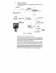
1.3 THEORY OF OPERATION A simplified block diagram of the FTB500 Mini Flow Signal Conditioner is shown in Figure 1-I. SENSITIVITY +v FTBBOO SIGNAL pcA_,,B CONDITIONER TURBINE FLOWMETER= MAIN CHASSIS CAPACITOR COUPLED FREQ. TO CONVERTER ANALOG OUTPUT OUTPUT AMP. Figure l-l. Block Diagram The basic operation of the system is as follows: The frequency signal from the flowmeter is connected to the FTB500 with a twisted pair shielded cable.
The signal entering the frequency to analog converter is passed through a combination of divide by N and DIP switch matrix. The output is chosen whose pulse rate is between 75 and 150 Hz at the maximum flow rate to be measured. This scaled pulse rate is fed into a precision monostable circuit. The output of the monostable is then filtered into an analog voltage that is proportional to flow.
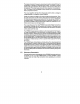
lL / UN LINEARIZED OUTPUT FLOW RATE (GPM) Figure 1-2. FTBSOO Output Characterlstlcs Diagram LINEARIZED 8 5 90 ! 7 .80 f u 1.00 I_7 UNLINEARIZED 10 50 100 % OF MAX IMUM FLOWRATE Figure 1-3.
Over the linear flow range, the input/output characteristics takes the form of: Equation 1 Frequency = C, x Flowrate-C, The FTB500 Series Turbine Meter requires the use of a linearization conditioner available in all OMEGA instrumentation. Accuracies of *l% of reading are typical after initial correction for offset. Better accuracies approaching *2% are possible using smart transmitters which can store the entire characteristics of the FTB500 Series Turbine Meter.
1.3.2 Viscosity Effects An ideal flowmeter may be defined as one in which the output is solely a function of the fluid flow being measured. Real flowmeters display dependencies on secondary fluid properties, such as viscosity temperature, and/or pressure. These effects tend to obscure or degrade the precision of the flow measurement. In very few flowmeter designs, the viscosity dependency is well understood and given suitable documentation, may be compensated for.
2.2 OPERATION Perform any purging of piping with spool piece in place. Once completed, install the flowmeter and connect cabling to pickup coil. With the FTB500 Mini Flow Signal Conditioner properly installed and calibrated, verify the following performance. With the power ON and no flow through the flowmeter, there should be no pulse output from the unit. To verify this, connect either a digital Frequency Counter or an AC voltmeter. If using a Digital Frequency Counter, the display should display zero.
The piping configuration immediately preceeding and following the flowmeter is termed the meter run. METER RUN -In general, the meter run should be chosen to have the same inner diameter as the meter bore. A minimum of IO pipe diameters of straight pipe upstream and 5 pipe diameters downstream are required. Where this optimum line configuration can not be implemented, it is advisable to install a flow straightener properly positioned upstream of the flowmeter.
It is common to transmit the low level output signal from the flowmeter several hundred feet through a shielded, twisted pair instrument cable. Where a noisy environment is suspect, it is recommended that a preamplifier be installed on or near the flowmeter to assure the preservation of flow information from the flowmeter to the electronic measuring system. Suitable accessory models are available from the manufacturer. 2.
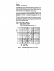
To -- 7x A I -\I 1 PICKUPCOIL :i I 1 ’ :,_ B .- --’ :, + ANALOG OUTPUT (STANDARD) 1 PULSE OUTPUT 1-P OPTION) 0 Lo SIGNAL - RETURN + SIGNAL _ 0 COMMON F(TEBT) @ TERMINAL BLOCK 1 0 @ 0 @ - DC VOLTAGE INPUT TERMINAL BLOCK 2 1234567 8 Figure 2-3. NOTE THE FTB500 IS EQUlPPED WITH AN INTEGRAL CALIBRATION SIGNAL. TO INJECT THIS TEST SIGNAL, INSTALL A JUMPER FROM TERMINAL 8 TO TERMINAL 1.
Xl PICKUP COIL Ayy==+--~ TERMINAL BLOCK 1 F(TEST) @ u IIBVAC (NEUTRALS 50160 Hz E INPUT TERMINAL BLOCK 2 NOTE THE FTB500 IS EQUIPPED WITH AN INTEGRAL CALIBRE \TlON SIGNAL. TO INJECT THIS TEST SIGNAL, INSTALL A JUMPER FROM TERMINAL 8 TO TERMINAL 1. Figure 24.
Connect the line power and ground to appropriate terminals. The line power should be an ‘instrument grade ’ line whose various loads do not contain solenoids, valves or other similar transient producing load which might adversely affect the operation of the system. Connect the cabling to the pulse output and to the inputs of the final measurement system. Observe same precautions listed for interconnecting cabling. SECTION 3 CALIBRATION 3.
3.3 l7I CONFIRM FTBSOO SIGNAL CONDITIONER OFFSET 1. Connect frequency counter to the offset frequency test point of the unit. 2. Inject the TEST frequency and observe that the frequency equals 10 x F(OS). For analog, go to Section 3.4. For pulse, continue to step 3. 3. Connect frequency counter to the output of the unit and with an injected TEST frequency, verify that the output frequency equals F(OUT) in the equation stated above. 3.4 CALIBRATION OF FTBBOO ANALOG OUTPUT 3.4.
where: F(TEST) F(OSl F(MAX) K Factor SPAN ZERO = test frequency used = offset frequency = the flowmeter output frequency at R(MAXl when at the reference condition at which the relation with F(MAX) was defined. = in units of readout, ifi, PULSE/GAL = varying component of analog output. For example, 16 mA for 4 to 20 mA output, 5V for 0 to 5V output = fixed offset component of analog output. For example, 4 mA for 4 to 20 mA output, OV for 0 to 5v output. 1.
FOR CURRENT OUTPUT OPTION ONLY 3. Connect a digital milli-ammeter or equivalent, across the current output terminals. 4. Adjust “ZERO” potentiometer (refer to Figure 3-l) for desired “ZERO” current (i.e., 4 mA). 5. Inject the test frequency while adjusting “SPAN” potentiometer (refer to Figure 3-l) so the current equals to SET (SPAN). 6. Repeat steps 4 and 5 until no change is observed. FOR VOLTAGE OUTPUT OPTION ONLY 7. Connect a digital voltmeter across the voltage output terminals. 8.
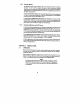
CORRECT OR IENTAT ION OF ROTOR WHEN ING LOOK DOWN FROM TOP -8 OW FL FL OW - DETA IL OF ROTOR WELO- Figure -1.
The FTB500 Flow m eter m ust be held in place by a vise. Me ter orientation should be such that the threaded plug is facing upwards. 2. Using a screwdriver and turning counter clockwise, break the seal and re move the plug. 3. Using tweezers or needle nose pliers, slowly pull the insert out, while taking care not to da m age the shaft or lose the thrust stop. 4. Remove the rotor by using a pair of tweezers. 5. Remove the shaft asse m bly with s m ooth needle nose pliers.
PCA-112 TO PICKUP COIL ACIDC POWER SUPPLY ANALOG OUTPUT ANALOG OUPUT COMMON PULSE OUTPUT COMMON FiTESTi - I BLK . 11 COIL-1 @ @ I-II- WHT GRN 0 Figure 5-1.
TROUBLESHOOTING GUIDE (Cont ’d) In case of an inoperable or malfunctioning system the following procedures can be used to isolate the faulty wiring, printed circuit boards and/or alternate causes. The majority of repairs can be made in the field thereby reducing the time a unit is out of service A recommended spare parts list is given in Section 6. The necessary documentation is contained within this manual with the exception of the calibration data sheet for the turbine flowmeter.
TROUBLESHOOTING GUIDE (Cont ’dl OBSERVED CONDITION Unit does not function Analog output. Analog output with no flow. CORRECTIVE ACTION I. PCA-115 has incorrect offset frequency setting. 2. Replace PCA-115. 3. Flowmeter used below or above normal range. Obtain correct flowmeter. 1. Replace PCA-112. 1. Turn sensitivity (SENS) potentiometer slowly ccw. NOTE Fully CCW will make the unit inoperative. 2. Replace PCA-112.
SECTION 8 SPECIFICATIONS INPUT POWER OPTION: 15 to 35 VDC at 75 mA (standard) 115VAC, 50/60 Hz (optional) INPUT Input protected, RF and band pass filtered, adjustable trigger level.
SPECIFICATIONS (Cont ’d) PULSE OUTPUTS (OPTIONAL): STANDARD OPTION -TTUCMOS fanout of IO TTL/CMOS loads. AC capacitively coupled square wave. OPTIONAL-Open collector -adjustable V,,, transistor 2N6660. Maximum OFF state voltage 60 VDC. Maximum ON current I.OA.
SPECIFICATIONS (Cont ’d) SPAN: A multiple turn adjustment potentiometer which is used to set the current/voltage output signal to the desired span corresponding to mA equivalent flow range (i.e., 4 to 20 mA or 0 to 1OV corresponding to O-100GPM). RESPONSE: A multiple turn adjustment potentiometer which is used to dampen the response at the analog output. SCALING FACTOR: A dual-in-line (DIP) switch located on the PCA-112 board which is used to select the desired pulse output scaling factor.
WARRANTY @zz OMEGA warrants this unit to be free of defects in materials and workmanship and to give satisfactory service for a period of 13 months from date of purchase. OMEGA Warranty adds an additional one (1) month grace period to the normal one (11 year product warranty to cover handling and shipping time. This ensures that OMEGA ’scustomers receive maximum coverage on each product. If the unit should malfunction, it must be returned to the factory for evaluation.
Where Do I Find Everything I Need for Process Measurement and Control? OMEGA...