
Owner's manual

4-20 mA Configurations
Device Settings: (Refer to Table 1 for details of this output option.)
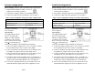
1) Using a small flat blade screwdriver, set the 10 position selector
switch to position 0.
2) Verify that the 2 position jumper JP1 is shunting pins 2 & 3.
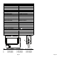
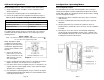
3) Connect the output connector to position B, as shown in Figure 3.
Table 3: (Field configurable settings for 4-20mA output option)
Configurable Control: Setting:
10 position selector switch Position 0
2 position jumper JP1 Pins 2 & 3 shunted
Output connector Position B
Input Voltage:
The supply voltage must be between 12 and 35 VDC. The maximum
resistance that may be placed within the current loop is given by the
following formula:
Rmax = 50(Vs - 12)
Rmax = the maximum resistance that may be placed in the current loop (?)
Vs = the value of the supply voltage (VDC)
NOTE: Although the signal
conditioning circuit does have
integral over-current protection,
manufacturer suggests that the
circuit be protected with a 0.25
amp fuse.
1) Connect the positive DC
power source (+12 to +35
VDC) to terminal # 1 on the
DIN connector or the red
wire on the pigtail.
2) Connect terminal #2 of the DIN connecter or the black wire from the
pigtail to the positive current input on the receiving device.
3) If the power source does not originate from the receiving device, the
negative side of the power supply must be connected to the signal
ground of the receiving device.
4) If the transmitter is operating properly, the green LED on the signal
conditioning board will illuminate dimly at zero flow and will increase
in intensity as flow increases.
Configuration / Operating Modes
Field Configurable Outputs
The FW1000 flow meter can be field configured to offer a variety of
output protocol signals. Possible outputs protocol options are 4-20mA,
0-5Vdc and 0-10Vdc. The following steps must be taken prior to making
any field configuration changes.
1) Fluid flow to the device should be shut off; the device must not be
under pressure.
2) The device should be disconnected from power prior to any field
calibration.
3) All safety protocols for the environment in which the device is
installed must be considered; remove the device from the installation
if needed.
4) Removing the cover will reveal the internal signal conditioning
circuitry and the field configurable controls. Figure 1 illustrates the
field configurable attributes of the device which shall be referenced
in subsequent sections of this manual.
Page 10 Page 7
Figure 3