
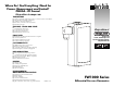
Owner's manual

0-5 Vdc Configurations
Device Settings: (Refer to Table 1 for details of this output option.)
1) Using a small flat blade screwdriver, set the 10
position selector switch to position 1.
2) Verify that the 2 position jumper JP1 is shunting pins 2 & 3.
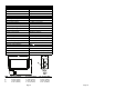
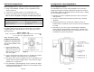
3) Connect the output connector to position A, refer to Figure 1.
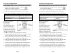
Table 1: (Field configurable settings for 0-5Vdc output option)
Configurable Control: 0-5 Vdc Setting:
10 position selector switch Position 1
2 position jumper JP1 Pins 2 & 3 shunted
Output connector Position A
Electrical Connection:
Refer to Figure 1
Input Voltage:
The supply voltage must be
between 12 and 35 VDC.
NOTE: The input impedance
(resistance) of the receiving
device must not be lower than
1000 ? or non-linearity may
result. Lower impedances will not damage the transmitter.
1) Connect the positive voltage source (+12 to +35 VDC) to terminal
#1 of the DIN connector or the red wire on the pigtail.
2) Connect terminal #2 of the DIN connector or the black wire from
the pigtail to the negative side of the DC voltage source.
3) Connect terminal #3 of the DIN connector or the white wire from
the pigtail to the 0-5 VDC input of the receiving device.
4) If the power source does not originate at the receiving device, a
wire will need to be connected between the negative side of the
voltage source and the signal ground of the receiving device.
5) If the circuit is operating correctly, the green LED on the circuit
board will illuminate brightly when power is applied to the unit.
Page 8
0-10 Vdc Configurations
Device Settings: (Refer to Table 2 for details of this output option.)
1) Using a small flat blade screwdriver, set the 10 position
selector switch to position 2.
2) Verify that the 2 position jumper JP1 is shunting pins 2 & 3.
3) Connect the output connector to position A, refer to Figure 1.
Table 2: (Field configurable settings for 0-10Vdc output option)
Configurable Control: 0-10 Vdc Setting:
10 position selector switch Position 2
2 position jumper JP1 Pins 2 & 3 shunted
Output connector Position A
Electrical Connection:
Refer to Figure 2
Input Voltage:
The supply voltage must be
between 12 and 35 VDC.
NOTE: The input impedance
(resistance) of the receiving
device must not be lower than
1000 ? or non-linearity may
result. Lower impedances will not damage the transmitter.
1) Connect the positive voltage source (+12 to +35 VDC) to terminal
#1 of the DIN connector or the red wire on the pigtail.
2) Connect terminal #2 of the DIN connector or the black wire from
the pigtail to the negative side of the DC voltage source.
3) Connect terminal #3 of the DIN connector or the white wire from
the pigtail to the 0-10 VDC input of the receiving device.
4) If the power source does not originate at the receiving device, a
wire will need to be connected between the negative side of the
voltage source and the signal ground of the receiving device.
5) If the circuit is operating correctly, the green LED on the circuit
board will illuminate brightly when power is applied to the unit.
Page 9
Figure 1
Figure 2