Table of Contents HMG-A Homogenizer Unit .................................................................................................................................... 4 Specifications: ..................................................................................................................................................... 4 Description: .........................................................................................................................................................
HMG-A Homogenizer Unit Specifications: Dimensions: Weight: Speed Range: 2.15"W x 7.875"H x 1.98"D (5.4 x 20.0 x 5.03cm) 1.4lb (0.6kg) 5,000 to 35,000 rpm (115v) Wattage: Voltage: Current: 144W 120v 50/60hz 1.2 amps (120v) Sample Volume Range: Noise Rating: Speed Control: Certification: 0.03ml to 1L 68dB Analog, variable speed, separate on/off switch , , (120v) Description: The HMG-A Homogenizer Unit is a high-speed dispersing and emulsifying apparatus for processing flowable or liquid media.
Operating Instructions: 1) Assembly of the homogenizer unit and stand (If using without stand assembly begin with step #2) a. Insert the 24" long support post into the hole located at the back of the base and tighten the 3/8" hex bolt. b. Loosen the locking knob on the motor support bracket and slide the homogenizer support bracket down over the end of the support post. c. Lock the homogenizer support bracket in place by tightening the locking knob. d.
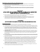
Environmental Conditions: Non-Operating Storage: Temperature: -20 to 65 deg. C (-4 to 149 deg. F) Humidity: 20% to 85% RH, non-condensing Operating Conditions: Temperature: 18 to 33 deg. C (64 to 91 deg. F) Humidity: 20% to 85 % RH, non-condensing Altitude: 0 to 6,562 ft. (2000 M) above sea level Installation Category II and Pollution Degree 2 in accordance with IEC 664. Safety 1) Never attempt to hold the lower end of the generator probe while it is attached to the homogenizer unit.
HMG-B Homogenizer Unit Specifications: Dimensions: Weight: Speed range: Wattage: Voltage: Current: 2.75"W x 9"H x 2.75"D (6.9 x 22.8 x 6.9cm) 3.2lb (1.4kg) 10,000 to 30,000 rpm 576W 120v 50/60hz 4.8 amps (120v) Sample volume range: Noise rating: Speed control: Certification: 0.03ml to 5L 72dB Variable speed, separate on/off switch, digital ready , (120v) Description: The HMG-B Homogenizer Unit is a hand-held or optional post-mounted 576 watt homogenizer with variable speed from 10,000 to 30,000 rpm.
3) Insert the power cord into the proper voltage outlet. 4) After all of the above assembly operations have been completed and the electrical connections checked, a test run on the homogenizer unit can be made. Do not use any generator probe at this time. **CAUTION** RUNNING A GENERATOR PROBE WITHOUT LIQUID MEDIA CAN CAUSE DAMAGE TO THE BEARINGS, UNLESS THE LOWER BEARING OF THE GENERATOR PROBE HAS BEEN REPLACED WITH A SEALED & SHIELDED STAINLESS STEEL BEARING.
Safety 1) Never attempt to hold the lower end of the generator probe while it is attached to the homogenizer unit. 2) Over tightening the rotor knife onto the rotor shaft can result in breaking the shaft and/or distortion of the rotor knife. 3) Any servicing of the homogenizer unit, except brush replacement, should be performed by an authorized Service Department. 4) Use of any accessories or attachments other than those supplied by the manufacturer may be hazardous and voids all warranties.
Attaching the Generator Probe to the Homogenizer Unit: 1) All generator probes are fitted to the homogenizer unit by inserting the upper end of the generator probe into the collar end of the homogenizer unit. 2) Align the vertical slots in the generator probe with the locating pins in the motor collar by rotating the generator probe. 3) Once aligned, push the generator probe inward as far as possible and turn the generator probe left.
Dismantling the Generator Probe: Dismantling the 5mm generator probe The following instructions are for the dismantling of only 5mm generator probe ONLY. 1. Unscrew the rotor knife from the bottom of the rotor shaft. Insert the 1/4" hex key (supplied in the tool kit) into the end of the rotor shaft collar and insert the screwdriver (supplied in the tool kit) into the rotor knife and turn the hex wrench counter clockwise. 2.
4. The rotor shaft should rotate freely within the generator probe tube and collar assembly. If the rotor shaft does not rotate freely, remove the rotor shaft from the tube and collar assembly and inspect both the upper and lower bearings for any possible damage. Replace any damaged bearings. 5. Insert the rotor knife into the end of the generator probe tube and collar assembly and rotate the knife clockwise while holding the rotor shaft collar. 6.
2. Find the correct lower bearing for your generator probe. a. Refer to the Generator Probe Drawings within this manual. b. Speak with an authorized Service Department that will assist you in finding the correct part. Upper SS bearing maintenance check: 1. Replacement of upper stainless steel bearing should be performed by an authorized Service technician. Mid-Bearing maintenance check: 1.
4) Once the Multi-Generator Probe has been inserted as far as possible into the Adapter, the bottom sleeve of the Adapter can be released. Releasing the bottom sleeve will lock the Multi-Generator Probe in place. Pulling gently on the Multi-Generator Probe will ensure that the Multi-Generator Probe is locked securely in place.
Perform a lower bearing maintenance check: 1. It is time to replace your lower Polytetrafluoroethylene (PTFE) bearing if... c. The inside diameter of the lower PTFE bearing fits loosely on the outside diameter of the shaft d. And/or you are able to wiggle and tilt the PTFE bearing 2. This item is the same for all Multi-Generator Probe. You will need to order the Multi-Generator Probe lower PTFE bearings from an authorized Service Department. Tips to maximize your Multi-Generator Probe performance: 1.
Generator Probe Index: Drawings and Spare Parts List 5mm, 7mm, and 10mm Generator Probes: Use the drawing below to assist with the generators listed.
20mm Generator Probe: Use the drawing below to assist with the generators listed.
Multi-Generator Probe Index: Drawing and Spare Parts List Multi-Generator Probe: Use the drawing below to assist with the generator probe list.