
Owner's manual


11
Dismantling the Generator Probe:
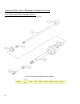
Dismantling the 5mm generator probe
The following instructions are for the dismantling of only 5mm generator probe ONLY.
1. Unscrew the rotor knife from the bottom of the rotor shaft. Insert the 1/4" hex key (supplied in the tool kit) into
the end of the rotor shaft collar and insert the screwdriver (supplied in the tool kit) into the rotor knife and turn
the hex wrench counter clockwise.
2. Remove the rotor knife from the bottom of the generator probe tube and collar assembly.
3. Draw the rotor shaft and rotor shaft collar assembly upwards out of the tube and collar assembly. The PTFE
(polytetrafluoroethlyene) washer can be removed from the rotor shaft.
4. Remove the lower bearing from the bottom of the generator probe tube and collar assembly. The lower bearing
should be replaced when worn before the rotor knife starts to rub against the side of the stator.
5. The rotor shaft collar assembly can be removed from the rotor shaft by loosening the set screw located at the
side of the rotor shaft collar using the hex wrench end of the screw driver (supplied in the tool kit).
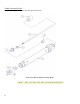
Dismantling 7mm, 10mm, and 20mm generator probes
The following instructions are for the dismantling of all other generator probes except 5mm.
1. Unscrew the rotor knife from the bottom of the rotor shaft. Insert the ¼” hex key (supplied in the tool kit) into
the end of the rotor shaft collar and insert the screwdriver end into the rotor knife and turn the hex wrench
counter clockwise.
2. Remove the rotor knife from the bottom of the generator probe tube and collar assembly
3. Remove the rotor shaft collar assembly by loosening the setscrew located in the side of the rotor shaft collar
from the rotor shaft using the hex wrench end of the screwdriver tool (For convenience, do not fully remove the
setscrew from within the rotor shaft collar assembly).
4. Remove the PTFE washer from the rotor shaft. Draw the rotor shaft downwards out of the generator probe tube
and collar assembly. (If rotor shaft does not slide out, press down on the rotor shaft from the top of the
generator probe tube and collar assembly using the hex wrench end of the screwdriver tool).
5. Remove the lower bearing from the end of the generator probe tube and collar assembly using the screwdriver.
The screwdriver should be inserted high enough to reach the inner side of the lower bearing. Put the flat side of
the screwdriver against the lower bearing, and then pull the handle of the screwdriver against the saw-teeth or
open-slotted end of the generator probe. The lower bearing should come out. The lower bearing should be
replaced when it shows signs of wear and before the rotor shaft collar starts to come in contact with the inside
wall of the motor collar or starts to rub on the top of the generator probe tube and collar assembly.
Assembly of the Generator Probe:
Assembling 5mm generator probe
The following instructions are for the assembly of only 5mm generator probe.
1. Insert the lower bearing into the bottom of the generator probe tube and collar assembly. Take the rotor knife
and place it into the bottom of the generator probe tube and collar assembly and push the lower bearing into its
proper location. The proper location is when the end of the rotor knife is flush with the bottom of the generator
probe tube and collar assembly.
2. Attach the rotor shaft collar to the end of the rotor shaft. Make sure that the setscrew in the rotor shaft collar
lines up with the flat on the end of the rotor shaft. The rotor shaft collar should be located as close to the end of
the rotor shaft as possible. Slide the PTFE washer up the rotor shaft until it contacts the rotor shaft collar.
3. Insert the rotor shaft with the rotor shaft collar and PTFE washer attached into the upper end of the tube and
collar assembly.