User's Guide http://www.omega.com e-mail: info @omega.
OMEGAnet On-Line Service http://www.omega.com Internet e-mail info@omega.com Servicing North America: USA : ISO 9001 Certified Canada : One Omega drive, Box 4047 Stamford, CT 06907-0047 Tel : (203) 359-1660 e-mail : info@omega.com 976 Bergar Laval (Quebec) H7L 5A1 Tel : (514) 856-6928 e-mail : info@omega.
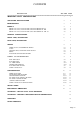
CONTENTS DESCRIPTION SECTION PAGE =========================================================================== IMPORTANT SAFETY CONSIDERATIONS 1 3 UNPACKING AND INSPECTION 2 4 MAIN FEATURES 3 4 MODELS 4 5 MODEL LDP-1XX-C0, DISPLAY TIME USING THE FORMAT MM : SS 4.1 5 MODEL LDP-1XX-C1, DISPLAY TIME USING THE FORMAT HH : MM 4.2 5 MODEL LDP-1XX-C2, DISPLAY TIME USING THE FORMAT HH : MM : SS 4.
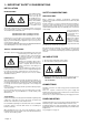
1.- IMPORTANT SAFETY CONSIDERATIONS INSTALLATION PRECAUTIONS.The installation and the future use of this unit must be done by suitable qualified personnel. The unit has not AC (mains) switch, it will be in operation as soon as power is connected. The installation must incorporate an external main switch. The unit has a protection fuse incorporated on the AC socket, if it is necessary to change or replace, use the time lag fuse according IEC 127/2 and the values indicated below.
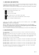
2.- UNPACKING AND INSPECTION It is advisable to do a detailed reading of this Manual before mounting the instrument. This Operator's Manual contains all the technical specifications : electricals as well as mechanics, both necessary to do a correct installation and also a good use of the instrument. At the same time the user will acquire the knowledge needed to obtain the best performances of the product.
The common features for all series are the following: MECHANICAL.- Housed in a rugged extruded aluminium profile housing for panel mounting or free standing. Finished in anodized black colour. The frontal lens is mounted with a special rubber profile which provides the front part of the unit with an IP-65 protection. CONTROL SIGNALS .- Three inputs, sharing one common return. The operating mode depends on interlinking of the three control lines CONNECTIONS.
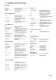
5.- GENERAL SPECIFICATIONS DISPLAY Type . . . . . . . . . . . . . . . . . Height digit . . . . . . . . . . . . Range máx. . . . . . . . . . . . . Brightness . . . . . . . . . . . . . 4 or 6 digits, 7 segments, red or green LED. 57 (2.3") or 100 mm. (4") 99 : 59 or 99 :59 : 59 Set by switch for 25%, 50%, 75% or 100% (normal). REAL TIME CLOCK . Type . . . . . . . . . . . . . . . . . 59 mm 59 ss (model C0) 12/24 hours selectable Time setting . . . . . . . . . . . .
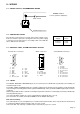
6.- FRONT VIEW, DESCRIPTION colon Models LDP-124-C0 & C1 LDP-144-C0 & C1 Display minutes for model C0 Display hours for model C1 Models Display seconds for model C0 Display minutes for model C1 LDP-126-C2 LDP-146-C2 Display hours for model C2 Display minutes for model C2 Display seconds for model C2 7.
8.- WIRING 8.1.- POWER SUPPLY, RECOMMENDED WIRING POWER SUPPLY 115 Vac (230 Vac Optional). Main switch FUSE and spare fuse. 8.2.- PROTECTION FUSES The unit has a protection fuse located on the power supply socket. If this fuse must be replaced or changed because the power supply is changed, use the time-lag fuse according to IEC 127/2 with the values indicated on the table. Power Supply Fuse value 230 Vac 115 Vac 0.2 A 0.4 A TABLE 4 8.3.
8.5.- EXCITATION VOLTAGE FOR SENSORS The unit supplies the Excitation Voltage for sensors, through control lines connector. If the current required for the sensors installed is more than 100 mA then do not use this terminal. Install other external power supply. See paragraph 5 for technical specifications 9.- POWER-UP AND OPERATION 9.1.- REAL TIME CLOCK At power-up, the unit displays the message MAStEr for 6 decade version or MASt for 4 decade version and will start to operate.
9.2.2.
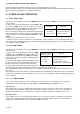
10.2.1- CONTROL BOARD POSITION Control board position for instruments series LDP-2X-CX Control board position for instruments series LDP-4X-CX 10.2.2- DIP SWITCH AND JUMPERS LOCATION JP1 JP2 JP3 JP4 ON JP10 JP9 JP5 OFF A JP8 JP7 B JP6 ON 1 2 3 4 5 6 7 8 9 10 11 1 2 OFF 10.2.
10.2.
11.- INSTALLATION 1.- Prepare a panel cut-out with the dimensions indicated on paragraph 12. 2.- Slide the instrument (1) into the cut-out. 3.- Slide the two fixation pieces (3) with T shape by both lateral sides of the instrument, such as it is shown on the drawing below. 4.- Turn the screw bolt until it is pressed firmly against the panel (4) and the instrument (1) remains totally fixed. 5.- The front part of the instrument has the necessary elements to provide an IP 65 protection.
APPENDIX 1: MODEL LDP-1XX-CX AS SLAVE REPEATER. FUNCTIONAL DESCRIPTION: Special configuration of Models LDP-1XX-CX for serial RS-422 repeater, to be used as slaves. The Serial port connection which is the only that keeps in operation, it is used to enter the data coming from the Master. The rest of functions and connections of these Models, remain disabled.
APPENDIX 2: TIME-NET CONFIGURATION AND CONNECTIONS. It is advisable to make the TIME-NET connections as follows: Transmitter Unit MASTER 1 Receiver Units SLAVE 2 3 SLAVE SLAVE n (maximum 32 units) 4 SLAVE SLAVE Connect RS-422 (JP1) line termination. Don’t connect RS-422 (JP1) line termination. Note Shielded twisted-pair cable, must be used for connections. SLAVE MASTER Don’t connect the cable shield to the receiver units (slaves).
WARRANTY/DISCLAIMER OMEGA ENGINEERING, INC. warrants this unit to be free of defects in materials and workmanship for a period of 13 months from date of purchase. OMEGA warranty adds an additional one (1) month grace period to the normal one (1) year product warranty to cover handling and shipping time. This ensures that OMEGA’s customers receive maximum coverage on each product. If the unit malfunction, it must be returned to the factory for evaluation.
Where Do I Find Everything I Need for Process Measurement and Control? OMEGA...