J .bemxa~eahnk@m_ Mtg:/~.umega.com e-mail: info@omega.
OMEGAneP On-Line Service http://www.omega.com Internet e-mail info@omega.com Servicing North America: One Omega Drive, Box 4047 USA: IS0 9001 Crrtifiod Stamford, CT 06907-0047 Tel: (203) 359-1660 e-mail: info@omega.com Canada: 976 Bergar Lava1 (Quebec) H7L 5Al Tel: (514) 856-6928 e-mail: canada@omega.
B Om ega Eng i nee r i ng i s t li ab no l e f o r an y m age da s r o pe r sona ln j u r y i , w ha t soeve r, esu lti ng r fr o m t he se f Om ega u ’ s o m as f l ow m e t e r s r con tr o o ll e r s w it h xy gen o s . A lt hough t he ga m ass f l ow m e t e r s and tr o ll e r s r e l eaned a c con r i o r o i t p m en sh t, w e m ake p c l a i m o r w a rr an t y t ha t he i r t c l ean li ne ss r ende r s t he m sa f e f o r oxy se r v i ce .
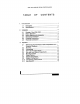
FMA-1900 SERIES FLOW CONTROLLERS CONT TABLE O 1 ................... 1 .Introduction 1 Description.. 1.1 2 .................. Specifications 1.2 4 2. .................... Installation 4 ................ FMA-1900 Receipt of Yo 2.1 4 Shipment.. .................. Return 2.2 5 ............... Before Beginn 2.3 7 ................. Mechanical 2.4 8 ................. Connections Plumbing 2.5 9 ................. Connections Electrical 2.6 .................... 11 3. Operation ...... Referencing th 3.
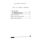
FMA-1900 SERIES FLOW CONTROLLERS CONTENT TABLE O F 3. Operation ( ................. 16 3.12 On/Off C 17 ............. 3.13 Purging of M 17 3.13.1 Gases ..................................... Purging 18 ................ Appendix A Pin Appendix .,........... B Pu 20 . . . . . . . . . Appendix C .K. . .
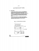
-I- INTROD 1.1 Description Omega’s FMA measure and c ranges from O (SCCM) to O-50 standard lite +1.5% of full scale o range, and tim point.
The flow versatile F rate direc The FMA-190 external output powe mA signals, which are provided f 15-pin “D” connector is point control. F rations with ei fittings, and w l&Specificat FLOW RATES fied are for an 21 .l “C (70°F). Othe nm3/h). SCFH or FMA-1900 SE (0.35-3.5 kg/cm*) differential kg/cm* PSI optimum. GASES: Most dioxide, argon wetted materia OUTPUT SIG mA into 100 load resistanc maximum load VDC supply).
ACCURACY fl.5% of O-100% full of scale full sc REPEATABILIW &0.25% of scale. full 0.08% of fu “C, or bette TEMPERATUR COEFFICIEN PRESSURE kg/cm*), or better: C RESPONSE T GAS PRESSU kg/cm*) gauge m kg/cm*) gauge optim 20 PSI (1.4 LEAK INTEGR locc/set ‘ of ATM helium to outside (Not recomm envir shutoff valve.
-2- INSTAL 2.1 Receipt of After receiving the packing ca packing carton their liability. A should be sub for detailed in Remove the p carton contain accessories a case of shorta (800~US Have your pur 2.
2.3 Before Beg Read the follow actual installat 1. Using the flow erly orient the flow l/4-inch line. pipe, If us yo quality paste p by hand, then avoid cracked The line press psig (10 kg/cm* gauge) or 1 operating pres 2. Apply power Omega 15-pin connec power “ D” tor on the side supply into lin power source specific powe 3. Upon applicatio level for the first flow) 4mA, dependin it will drop ration). Allow a CAUTION: The FMA-19 Do NOT mA output apply or 4. After the warm monitoring the 5.
Integral l/2 digitDisplay LCD d 6 engineering u scale range a The decimal p will show auto %). 7. Overrange co output going After the over take several m resume norm 8. The FMA-190 ments due to Becaus is operated in cannot be tole a regulated 2 peak, and cap The standard VDC. It is pos reduced perfo between the a flow rate.
2.4 Mechanical CAUTION: The in which your F kg/cm* gauge) (5O” respecti C), or 1 150 psig (10 In order to ens tubing or piping your FMA-190 clean gas only may clog the s period of time. high-efficiency FMA-1900. Do not locate t temperature ch significant amo connectors and transducer poi results if you o was calibrated its calibrated p mance problem CAUTION: Do n inside Instead, or outsid mo Mount #6, the type “ selfB” FMA tapping screws CAUTION: The furtherthan .15” If (4mm). screws .
$5_ Plumbing C Your FMA-190 (standard) outlet fittings. or co T should not be cleaned or cal l/4-inch pipe requires a goo should be use only one and a CAUTION: Ov fittings or shiicalibrat For l/4-inch installation (outside d fittings, simply the tubing res nut is finger-tig Scribe the n While holding tighten the nu mark make on o’clock positio snugging a back-up wrench to avoid with damaging the inlet fitting.
TABLE 2-1 (Under Standard AP Conditions of 39 PSIG Inlet and Ambient Outlet) TY Flow Valve Ranges Orif Relative (Typical-in to N O-10 0.02 to O-500 0.03 O-500 to O-l 00 0.05 O-2 to O-5 SLM O-10 0.05 SLM O-l 5 0.065 SLM 0.083 O-30 SLM to O-50 2.
Figure 2-2 “D” Connector Location and Pin Number Assignments TABLE 2-2 “D” CONNECTOR PIN ASSIGNMENTS PIN # FUN FUNCTION PIN # 9 4-20 mA (Comm SignalCommon Signal Co O-5 10 VDC Flow +5 VDC Ref 11 valve Return 12 Valveoff +24 VDC VDC) (15 Suppty 13 PowerCommo 14 4-20 mA Output No Connection 15 ChassisG +24 VDC (15 VDC Setpoint Input NOTE: +15 VDC operat #8.
OPERA 3.1 Referenc m Temperatu The gas flow r 760 mm of m “standard” 21.1 “C (70°F) and co (one atmosphe order. Be sure your you k FMA-1900, be comparing the meter. For exa approximately 0°C rather .l”C. tha a “standard” t 3.2The Accuracy 51.5% accuracy of full sc effective contr &1.5% of full scale a kO.075 VDC * 0.150 (O-l is accurate to mA output is a VDC) and the f0.24mA This means, fo It0.24mA. Please kO.075 VDC or can be as high get an output s two ranges, yo respect to the 1.5% times the tag.
Overrangin 3.3 If the flow rate FMA1900 data tag higher value. T overranged flo an overrange and 4-20 mA outputs can or more. On th four digits 199 digits “1’ will will blan app display. Overrange conditions by the andlor output displa ar going hii level, to above a t condition has the FMA-1900 overrange con 3.
Zero Setpoint Adjustm and Lo The setpoint potentiomet zero and loc ports marked o is fl.5% more thanyo of scale, ometer when y reached its no flow at the des The local setpoint potentiome using an exter wise increases Mounting P Unless specifie brated for insta (k15”) with the enclo position is diffe NOTE: The ze when under pr Output Opt The standard o signal th VDC 4-20 mA (O-l 0 VD linearly toflow the O-100% mass VDC (and O-1 mA output a resistance of 2 dates a load re 500 Ohms at 1 3.
Figure 3-2 Component Location and 7 D/P Switch Set Up r- Lj r-- ’ I II___ .
3.9 Setpoint Configura m - The DIP switche configure setpoint operation an The default setpoint using conf th on-board setpoint command po in the case) and Other options in setpoint with positive s mA setpoint with positiv sourced 4-20 A factory installe Move 1 to the DIP right switc ( setpoint potentiometer external setpoin required if you setpoint potentiom Move DIP switc mA setpoint input.
3.10 Cold Sens FMA-1900 con the valve whe uncontrolled fl monitoring the the output hig There are sev a) Operation at instrument is ra b) Power failu resumption of p operating temp c) Sensorfailur The operation o output upon pow (The output first 10 to 20 se drop 4mA, depending to output you 0 are VDC observing.) 3.11 Auto Shut-O All FMA-1900 feature that, w signal level of To enable this to the right.
3.13 Purging of The purge fun for the purpos flushing unwa valve is opene the rated full s uncontrolled n must be met b 1) The Valve OF or open state 2) The Auto-Shu setpoint command s scale or DIP The activation Auto-Shutoff f To activate 15-pin “ conne D” pu tor to common open-collecto at least 4mA ( appearing on 3.13.1 Purging N Purge non-re dry nitrogen o 3.13.2 Purg Purge reactiv following meth Cycle 1) purge.
Appendix A.
Appendix C. K-factors and Gas Tables The following properties of g and meters. T 1. Calibrating patticuan latly useful if sothe a called “nasty ” 2. Interpreting th calibrated wit In the applying tables, the fo Q,/Q,=K (1) where: Q = The volumetr 0°C and 760 m conditions of K = The “K” factor (6), ), = (refers defin refers ‘?eferen gas.
The mass ri-r= pQ flow (3) where: p = The gas (gil); ma p is given 780 in mm the H 0°C AT, is proportio temperature d voltage, E, of AT=aE (4) where: A a = contstant If we (4) combine insert the (2) and Q, we solve get: for Q = PC,) (bN/ (5) where: H/aE = A constan b = For ourQ,, purpos for an to prod actual Q,, gas to t the same outp We get this by comgining Equations (6) Q,/Q,=K,/K Q,,) Please note th the fundament For convenien the ratios K,/K2, instead of th In the third col where the re Ka*
EXAMPLE (N,) 1: and the flow ra The flow rate Qco, / QN* = Kco, / KN*, or Qco, = /1 (0.74 = .OOO) 740 SCC 10 EXAMPLE (H,)2: and the flow ra found.as is follows The (N,O) flow rate QN*O / QH* KN*O = / KH*, or QN*O = (0.71 /1 .Ol) 100 Please note th used in each case EXAMPLE 3: use with (SiH CL,) dichlo at a preterred reference flow. We wish (CF,). What CF, must flow we of g QSIH~C~ / QCF’ = KsiH2Ch / KcF,, 100 / QCF’ = 0.869 QCF’ = 100/0.
Achul on Acetylene u-tat. Ch.“dul Sytt’bol z CJ’, Air Ret. to Rd.Ws K-k Cp Rel. to (CwQ) N, BensKy EIeakUhef (g/l) o-ring valv e 80% seat N, se .4036 N, 1.00 .246 1.293 1.162 Aflene (Propadiie) C,“, N’ .43 ,352 1.767 Ammonia NH, N, .73 ,492 ,766 KR NE0 NE0 KR KR Argon A’ A’ t.ooO .1244 1.762 Arsine AsH, N, .67 .1167 3.476 Boron Trichlodda BC’, N, .41 .1279 5.227 Boron Trtftuoride BF, N, 51 .1776 3.025 Bromine B’, N, .61 .0539 7.
Acluol GOO chornlcel Ref Symbol Gas Deulerium Elastomer De ’tac (g6) O-ring ’ Vatw 80% Seat 100 .1722 .&I so6 7.235 Nz .I9 .I5 9.362 KR N, .47 .075 7.76 KR CCI ’F, N’ .35 .I432 5.395 KR CHCI,F N* .;2 ,140 4.952 KR Dibromethane Dichiorodifluommethane K&c. Cp Rel. to (Cat/g) N, % 49 CBr ’F ’ Dibromodifluoromethane K-fttG. Ret. to Ret.Gas Y D, Diborane . 1.799 KR (Freon-12) Dichlorolluoromethane (Freon-21) (CH,),SiCI, N, .25 .tS62 5.
Actual G8o ChOltliCSf svmbol Helium HexaRuoroalhane K-M. K-fee. C p to Ref. to (CalIo) ReL R&Gas N, 1.464 He He 1.6’36 C’F, N, .24 Elutottle’ (grl) O-ring ’ Valve 00% Seat DSllSity 1.241 .17&T .1834 6.157 KR .3966 3.645 KR 3.419 6699 (Freon-1 16) Hexane C,H,, N, .16 “* H, t.006 Hydrogen 1.0, Hydrogen Bromide HBr N, 1.066 .0661 Hydrogen Chloride HCI N, 1.006 .1912 Hydrogen Cyanide HCN N, t ,070 .317f 1.206 Hydnqen fluoride HF N, t.
Actual Gas Chemical Raf. Symbol Gas Octafluorqclobutane C,F, Y OF, 0, K-faC. K-fsc. Cp Rel. to Ral. to (Calfg) Ref. Gas N, DenSity Efaatornu A(& O-ring ’Valv e Seat .17 ,165 6.397 N, .63 .1917 2.406 Y 1.000 .2193 1.427 KR (Freon-Csr 6) Oxygen Difluodde Oxygen Ozone 0, N, ,446 .3 2.144 Pentaborane B,H, N1 .26 .36 2.616 Pentane 4H ’z N, 21 ,396 3.219 Perchloryi Fluoride CIOaF .39 ,151 ’ 4.571 KR KR KR C,F, N, N, ,174 ,197 6.366 KR Phosgene COCI, N, .44 .
WARRANTY/DISCLAIMER OMEGA ENGINEERING, INC. warrants this unit to be free of defects in materials and workmanship for a period of 13 months from date of purchase. OMEGA Warranty adds an additional one (1) month grace period to the normalone (1) year product warranty to cover handling that OMEGA ’s customers receive and maximum coverage on each product. sh If the unit should malfunction, it must be returned to the factory for evaluation.
Where Do I Find Everything I Need for Process Measurement and Control? OMEGA...Of Course! TEMPERATURE Ii?? Thermocouple, RTD & Thermistor Probes, Connectors, & Thermistor 0 Calibrators & Ice Point References 0 Recorders, Controllers & Process Monitors 0 Infrared Pyrometers Panels & Assemblies @’ Wire: Thermocouple, RTD PRESSURE, STRAIN AND FORCE .