User’s Guide Shop online at omega.com e-mail: info@omega.com For latest product manuals: omegamanual.info OMB-DAQBOARD-3000 Series P OMB-1128-0901 rev 1.
OMEGAnet ® Online Service omega.com Internet e-mail info@omega.com Servicing North America: U.S.A.: ISO 9001 Certified Canada: One Omega Drive, P.O. Box 4047 Stamford, CT 06907-0047 TEL: (203) 359-1660 e-mail: info@omega.com 976 Bergar Laval (Quebec) H7L 5A1, Canada TEL: (514) 856-6928 e-mail: info@omega.ca FAX: (203) 359-7700 FAX: (514) 856-6886 For immediate technical or application assistance: U.S.A.
Warnings, Cautions, Notes, and Tips Refer all service to qualified personnel. This symbol warns of possible personal injury or equipment damage under noted conditions. Follow all safety standards of professional practice and the recommendations in this manual. Using this equipment in ways other than described in this manual can present serious safety hazards or cause equipment damage.
Your order was carefully inspected prior to shipment. When you receive your order, carefully unpack all items from the shipping carton and check for physical signs of damage that may have occurred during shipment. Promptly report any damage to the shipping agent and your sales representative. Retain all shipping materials in case the unit needs returned to the factory. CAUTION Using this equipment in ways other than described in this manual can cause personal injury or equipment damage.
Table of Contents DaqBoard Installation Guide (p/n 1033-0940) 1 – Device Overviews Block Diagrams …..
– Setpoint Configuration for Output Control Overview …… 6-1 Detecting Input Values …… 6-3 Controlling Analog, Digital, and Timer Outputs …… 6-4 P2C, DAC, or Timer Update Latency …… 6-6 More Examples of Control Outputs …… 6-7 Detection on an Analog Input, DAC and P2C Updates …… 6-7 Detection on an Analog Input, Timer Output Updates …… 6-8 Using the Hysteresis Function …… 6-8 Using Multiple Inputs to Control One DAC Output …… 6-10 7 – Specifications - DaqBoard/3000 Series and PDQ30 Appendix A: DBK215 16-Co
This product requires one of the following Operating Systems: Windows 2000 Windows XP
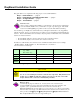
DaqBoard Installation Guide This guide tells how to complete the following steps for a successful installation. Step 1 – Step 2 – Step 3 – Step 4 – Install Software …… page 2 Install Boards in Available PCI Bus-Slots …… page 3 Configure Boards ….. page 5 Test Hardware ….. page 6 Reference Note: After you have completed the installation you should refer to the electronic documents that were automatically installed onto your hard drive as a part of product support.
Reference Note: Adobe PDF versions of user manuals will automatically install onto your hard drive as a part of product support. The default location is in the Programs group, which can be accessed from the Windows Desktop. Refer to the PDF documentation for details regarding both hardware and software. Note that hardcopy versions of the manuals can be ordered from the factory.
Step 2 – Install Boards in available PCI Bus-slots IMPORTANT: Software must be installed before installing hardware. CAUTION Turn off power to, and UNPLUG the host PC and externally connected equipment prior to removing the PC’s cover and installing the DaqBoard. Electric shock or damage to equipment can result even under low-voltage conditions. Take ESD precautions (packaging, proper handling, grounded wrist strap, etc.) Use care to avoid touching board surfaces and onboard components.
7. 8. 9. 10. 11. 12. 13. Refer to the figure at the right. Align the groove in the DaqBoard’s PCI edge-connector with the ridge of the desired PCI slot, and with the PC’s corresponding rearpanel slot. Push the board firmly into the PCI slot. The board will snap into position. Secure the board by inserting the rear-panel adapter-plate screw. Using the previous steps, install additional boards into available PCI bus-slots, if applicable to your application. Replace the computer’s cover.
1. Run the Daq Configuration control panel applet. Navigation from the desktop to the applet is as follows: Start ⇒ Settings ⇒ Control Panel ⇒ Daq*Configuration (double-click) 2. Double-click on the Device Inventory’s DaqBoard1K0, 2K0, or 3K0 icon, as applicable. The DaqBoard’s Properties tab will appear. If the DaqBoard icon is not present, skip to the upcoming Using ‘Add Device’ section. 3. Enter a “Device Name” in the text box, or use the default, e.g., DaqBoard2K0.
Step 4 – Test Hardware Use the following steps to test the DaqBoard. Note that these steps are continued from those listed under the previous section, “Configure Board.” 1. Select the “Test Hardware” tab. 2. Click the “Resource Test” button. 3. After the test is complete, click “OK.” System capability is now tested for the DaqBoard and a list of test results appears on screen.
IG-8 DaqBoard Installation Guide 918494 1033-0940, rev 8.
Device Overviews 1 Block Diagrams …… 1-1 Connections …… 1-2 Product Features …… 1-3 Software ……1-13 DaqView can only be used with one DaqBoard at a time. DASYLab and LabView can be used with multiple boards. For multiple board use (via custom programming) refer to the Using Multiple Devices section of the Programmer’s Manual. Reference Note: Programming topics are covered in the Programmer’s User Manual (p/n 1008-0901).
Block Diagram for DaqBoard/3005 and /3006 * Note: DaqBoard/3006 has 16 single-ended analog inputs; ±10V input range only; it has no differential input. DaqBoard/3006 has no HDMI interface. Connections Reference Note: For the DaqBoard/3000 Series installation procedure, refer to the DaqBoard Installation Guide (1033-0940). A copy of the guide is included at the beginning of this manual. SCSI - 68 pin HDMI All input and output signals are available at the 3000 Series board’s 68-pin SCSI connector.
Product Features I/O Comparison Matrix Product or System Analog Input Channels Input Ranges Analog Output Channels Digital I/O Channels Counter Inputs Timer Outputs DaqBoard/3000 16SE / 8DE 7 2 24 4 2 DaqBoard/3001 16SE / 8DE 7 4 24 4 2 DaqBoard/3005 16SE / 8DE 7 0 24 4 2 DaqBoard/3006 16SE only 1 0 24 4 2 DaqBoard/3000 with PDQ30 64SE / 32DE 7 2 24 4 2 DaqBoard/3001 with PDQ30 64SE / 32DE 7 4 24 4 2 DaqBoard/3005 with PDQ30 64SE / 32DE 7 0 24 4 2 The
Signal I/O One 68-pin connector provides access to the 16SE/8DE analog input channels, 24 digital I/O lines, counter/timer channels, and analog outputs (when applicable). With exception of DaqBoard/3006, a HDMI connector is also located on the orb. The HDMI provides connection for channel expansion with the PDQ30. Orb with HDMI and 68-Pin SCSI Connectors Note: The HDMI connector is not present on the DaqBoard/3006.
Another synchronous mode allows digital inputs to be scanned every time an analog input channel is scanned. For example, if eight analog inputs are scanned at 1 µsec per channel continuously, and 24 bits of digital inputs are enabled, then the 24 bits of digital inputs will be scanned at 24 bits per 1 µsec. If counters are enabled in this mode, they will be scanned at once per scan, in the same manner as in the first example above.
Example 2: Analog channel scanning of voltage and temperature inputs The figure below shows a more complicated acquisition. The scan is programmed pre-acquisition and is made up of 6 analog channels (Ch0, Ch2, Ch5, Ch11, Ch22, Ch23.) Each of these analog channels can have a different gain. Two of the channels (22 and 23) are from a PDQ30 expansion module. These two channels can be programmed to directly measure thermocouples.
Example 3: Analog and digital channel scanning, once per scan mode The figure below shows a more complicated acquisition. The scan is programmed pre-acquisition and is made up of 6 analog channels (Ch0, Ch2, Ch5, Ch11, Ch22, Ch25) and 4 digital channels (16-bits of digital IO, 3 counter inputs.) Each of the analog channels can have a different gain and each of the counter channels can be put into a different mode (totalizing, pulsewidth, encoder, etc.
Example 4: Sampling digital inputs for every analog sample in a scan group The figure below shows another acquisition. The scan is programmed pre-acquisition and is made up of 6 analog channels (Ch0, Ch2, Ch5, Ch11, Ch22, Ch25) and 4 digital channels (16-bits of digital input, 3 counter inputs.) Each of the analog channels can have a different gain and each of the counter channels can be put into a different mode (totalizing, pulsewidth, encoder, etc.
Bus Mastering DMA The DaqBoard/3000 series supports Bus Mastering DMA. Multiple DMA channels allow analog and digital/counter input data, as well as analog and digital output data to flow between the PC and the DaqBoard/3000 series without consuming valuable CPU time. The driver supplied with the DaqBoard/3000, as well as all other third-party software support such as LabVIEW®, automatically utilize Bus Mastering DMA to efficiently conduct I/O from the PC to the DaqBoard.
o Variable pre-trigger with post trigger stop event. Unlike the previous pre-trigger modes, this mode does not have to satisfy the pre-trigger number of readings before recognizing the trigger event. Thus the number of pre-trigger readings acquired is variable and dependent on the time of the trigger event relative to the start. In this mode, data continues to be acquired until the stop trigger event is detected. Driver support only. o Variable pre-trigger with infinite post trigger.
Digital Inputs and Outputs Twenty-four TTL-level digital I/O lines are included in each of the DaqBoard/3000 Series boards. Digital I/O can be programmed in 8-bit groups as either inputs or outputs and can be scanned in several modes (see Input Scanning). Ports programmed as input can be part of the scan group and scanned along with analog input channels, or can be asynchronously accessed via the PC at any time, including when a scanned acquisition is occurring.
This example has all 4 DACs being updated and the 16-bits of digital IO. These updates are performed at the same time as the acquisition pacer clock (also called the scan clock.) All 4 DACs and the 16-bits of pattern digital output are updated at the beginning of each scan. Note that the DACs will actually take up to 4 us after the start of scan to settle on the updated value.
Timer Outputs Two 16-bit timer outputs are built into every 3000 series board. Each timer is capable of generating a different square wave with a programmable frequency in the range of 16 Hz to 1 MHz. Example 6: Timer Outputs Timer outputs are programmable square waves. The period of the square wave can be as short as 1us or as along as 65535 us. See the table below for some examples. Divisor Timer Output Frequency 1 100 1 MHz 10 kHz 1000 10000 1 kHz 100 Hz 65535 15.
Ready-to-use programs are convenient for fill-in-the-blank applications that do not require programming for basic data acquisition and display: • • • • DaqView is a Windows-based program for basic set-up and data acquisition. DaqView lets you select desired channels, gains, transducer types (including thermocouples), and a host of other parameters with a click of a PC’s mouse. DaqView lets you stream data to disk and display data in numerical or graphical formats.
Connections and Pinouts 2 Overview …… 2-1 Pinout for DaqBoard/3000 Series Boards …… 2-2 TB-100 Terminal Connector Option …… 2-3 PDQ30 Analog Expansion and DBK215 Connector Options …… 2-4 CAUTION Turn off power to all devices connected to the system before connecting cables or setting configuration jumpers and switches. Electrical shock or damage to equipment can result even under low-voltage conditions. CAUTION The discharge of static electricity can damage some electronic components.
Pinout for DaqBoard/3000 Series Boards Pin numbers refer to the 68-pin SCSI female connector, located on the DaqBoard/3000.
TB-100 Terminal Connector Option The TB-100 Terminal Connector option can be used to connect all signal I/O lines that are associated with a DaqBoard/3000 Series device. TB-100 connects to the DaqBoard’s 68-pin SCSI connector via a 68-conductor cable: p/n CA-G55, CA-G56, or CA-G56-6. TB-100 Pinout Screw Terminals for TB2 Side The “Pin” column refers to the pin no. on the 68-Pin SCSI Connector.
PDQ30 Analog Expansion and DBK215 Connector Options PDQ30 Analog Expansion Module DBK215 16 BNC Connector Module DaqBoard/3000 Series boards can connect to optional devices through either or both of the board’s orb connectors. DaqBoard/3000 Series Connector Layout* *Note: DaqBoard/3006 has no HDMI Connector and cannot be connected to a PDQ30. o The HDMI connector can be used to connect a PDQ30 Analog Expansion Module to a DaqBoard/3000 Series board [other than a DaqBoard/3006]. A CA-266-3 (3-ft.
DBK215 If you are not using a TB-100 terminal board connection option with your DaqBoard/3000 Series board you can, instead, make use of a DBK215 module. The DBK215 includes: o o o o BNC Access to 16 inputs or outputs (on front panel) on-board screw-terminal blocks* on-board socket locations for custom RC Filter networks* 68-pin SCSI connector (on rear panel) * The top cover plate must be removed to access the terminal blocks and the RC filter network section of the DBK215’s board.
System Example A DaqBoard/3000 Series system example which includes both a PDQ30 and a DBK215 is illustrated on page 2-4. For convenience, it has been repeated below. In regard to the PDQ30 aspect: 1) 2) 3) 4) 5) Connection from PDQ30 to DaqBoard/3000 is made via a CA-266-3 (or CA-266-6) HDMI cable. PDQ30’s analog input lines connect via removable screw-terminal blocks (TB1 through TB6). A pinout for PDQ30 follows shortly. Users of DBK215 should refer to Appendix A.
PDQ30 Terminal Block Pinouts (TB1 through TB6) PDQ30 can measure 48 channels of voltage or 24 channels of temperature. The temperature measurement requires the use of Differential Mode. Reference Notes: For PDQ30 specifications, refer to chapter 6.
2-8 Connections & Pinouts 918494 DaqBoard/3000 Series User’s Manual
CE-Compliance 3 Overview ……3-1 CE Standards and Directives …… 3-1 Safety Conditions ……3-2 Emissions/Immunity Conditions ……3-2 Overview CE standards were developed by the European Union (EU) dating from 1985 and include specifications both for safety and for EMI emissions and immunity. Now, all affected products sold in EU countries must meet such standards.
For clarification, terms used in some Declarations of Conformity include: • pollution degree: any addition of foreign matter, solid, liquid or gaseous (ionized gases) that may produce a reduction of dielectric strength or surface resistivity.
Calibration 4 DaqBoard/3000 Series boards are factory-calibrated. However, if adjustments are needed they should be completed in the following order: 1. Analog Measurement Path, Offset and Gain 2. Voltage Reference 3. DAC0 Offset and Gain * 4. DAC1 Offset and Gain * 5. DAC2 Offset and Gain * 6.
4-2 Calibration 918494 DaqBoard/3000 Series User’s Manual
DaqCal User Calibration Utility Contents Overview …… i Equipment …… ii NIST Traceability …… iii Installing DaqCal …… iii Setup …… iii What to Expect when using DaqCal …… v Calibrating Analog Outputs …… vii Calibrating DBK Expansion Options …… viii CAUTION Turn off power to all devices connected to the system before connecting cables or setting configuration jumpers and switches. Electrical shock or damage to equipment can result even under low-voltage conditions.
Equipment Refer to the appropriate block below, depending on whether you will be calibrating through a 37-pin, 68-pin, or 100-pin connector. P1 37-PIN If calibration signals will be passing through a 37-pin P1 connector you will need: Required: 6.
NIST Traceability Calibration test equipment should be traceable through the National Institute of Standards and Technology. (NIST). Customers not familiar with traceability through that institute should contact them at traceability@nist.gov The NIST Policy on Traceability (contained in NIST Administrative Manual, Subchapter 5.
P1 (37-pin) For DB37 P1 applications you can attach a DBK11A to the device via a CA-37 cable. Connecting a DBK11A P4 (100-pin) For 100-pin P4 connector applications you can use a DBK200 (or DBK201), DBK11A, and a CA-195 cable; or you could use a DBK213 and a CA-195 cable. Illustrations of these two scenarios follow. Connecting a DBK11A via a DBK200 Connecting a DBK213 * There are several DBK200 Series adaptive boards and modules available for 100-pin P4 connector applications.
After you have completed the setup according to the type of device and appropriate connectivity option, launch DaqCal and follow the on-screen instructions. What to Expect when using DaqCal When DaqCal opens you will be prompted to select your device from a list. After doing so the application will guide you through the calibration process using simple on-screen instructions. It is important that you select the correct device as the steps required usually differ from one device to another.
From the screen’s Calibration List (right-hand figure), select the desired types of calibration. In the example shown we have selected: o o Channel Offset A/D (Single-Ended) Channel Gain A/D (Single-Ended) After making the selections, click the button (see preceding figure). Steps specific to your device will now display. Selecting the Desired Calibrations Follow the on-screen instructions for your device.
Calibrating Analog Outputs After launching DaqCal, select the device to be calibrated from the device inventory list. After selecting your device, click the button. An instruction screen with a Calibration List will display. From the screen’s Calibration List select the desired types of calibration. For the example we have selected: o System Positive Reference D/A o System Negative Reference D/A After making the selections, click the button (see preceding figure).
Calibrating DBK Expansion Options If the primary data acquisition device (DaqBook, or DaqBoard) is out of its calibration period, calibrate that device prior to calibrating the DBK expansion option. An alternative to using DaqCal is to contact the factory or your service representative to schedule a factory calibration. After launching DaqCal, select the device to be calibrated from the device inventory list. After selecting your device click the button.
Counter Input Modes 5 Debounce Module …… 5-1 Terms Applicable to Counter Modes…….5-5 Counter Options …… 5-5 Counter/Totalize Mode …… 5-6 Period Mode …… 5-8 Pulsewidth Mode …… 5-11 Timing Mode …… 5-13 Encoder Mode …… 5-15 Each of the high-speed, 32-bit counter channels can be configured for counter, period, pulse width, time between edges, or encoder modes. Debounce Each channel’s output can be debounced with 16 programmable debounce times from 500 ns to 25.5 ms.
Trigger After Stable Mode In the “Trigger After Stable” mode, the output of the debounce module will not change state until a period of stability has been achieved. This means that the input has an edge and then must be stable for a period of time equal to the debounce time. Debounce Module – Trigger After Stable Mode The following time periods (T1 through T5) pertain to the above drawing.
T2 – During time period T2, the input signal is not stable for a length of time equal to T1 (the debounce time setting for this example.) Therefore, the output stays “high” and does not change state during time period T2. T3 – During time period T3, the input signal is stable for a time period equal to T1, meeting the debounce requirement. The output is held at the high state. This is the same state as the input. T4 – At anytime during time period T4, the input can change state.
Use trigger before stable mode when the input signal has groups of glitches and each group is to be counted as one. The trigger before stable mode will recognize and count the first glitch within a group but reject the subsequent glitches within the group if the debounce time is set accordingly. The debounce time should be set to encompass one entire group of glitches as shown in the following diagram.
Terms Applicable to Counter Modes The following terms and definitions are provided as an aid to understanding counter modes. Gating: Any counter can be gated by the mapped channel. When the mapped channel is high, the counter will be allowed to count, when the mapped channel is low, the counter will not count but hold its value. Mapped Channel: A mapped channel is one of 4 signals that can get multiplexed into a channel’s counter module.
Encoder Mode (see page 15). OPT[1:0]: Determines the encoder measurement mode: 1X, 2X, or 4X. OPT2: Determines whether the counter is 16-bits (Counter Low); or 32-bits (Counter High). OPT3: Determines which signal latches the counter outputs into the data stream going back to the /3000 Series board. Start of scan or mapped channel. OPT4: Allows the mapped channel to gate the counter. OPT5: Allows the mapped channel to clear the counter for Z reference.
An explanation of the various counter options, depicted in the previous figure, follows. COUNTER: OPT0: This selects totalize or clear on read mode. Totalize Mode – The counter counts up and rolls over on the 16-bit (Low Counter) boundary, or on the 32-bit (High Counter) boundary. See OPT2 in regard to choosing 16-bit or 32-bit counters.
Period Mode TIP: When using a counter for a trigger source, it is a good idea to use a pre-trigger with a value of at least 1. The reason is that all counters start at zero with the initial scan; and there will be no valid reference in regard to rising or falling edge. Setting a pre-trigger to 1 or more ensures that a valid reference value is present, and that the first trigger will be legitimate. This mode allows for period measurement of the channel input.
PERIOD: OPT[1:0]: Determines the number of periods to time, per measurement. This makes it possible to average out jitter in the input waveform, sampling error, noise, etc. There are four options: (1) The channel’s measurement is latched every time one complete period has been observed. (2) The channel’s measurement is latched every time that 10 complete periods have been observed. The value that gets returned is equal to 10 consecutive periods of the input channel.
Upper 16-bits of the 32-bit counter Range (Hz) Ticksize (nS) 15u – 1500u 150u – 15m 1500u – 150m 15m – 1500m 150m – 15 1500m – 150 15 – 1500 20833.333 Averaging Option 1 2083.333 208.333 20.833 20.833 20.833 20.833 1 1 1 10 100 1000 Lower 16-bits of the 32-bit counter Range (Hz) Ticksize (nS) 1 – 100 10 – 1k 100 – 10k 1k – 100k 10k – 1M 100k – 5M 1M – 5M 20833.333 Averaging Option 1 2083.333 208.333 20.833 20.833 20.833 20.
Pulsewidth Mode TIP: When using a counter for a trigger source, it is a good idea to use a pre-trigger with a value of at least 1. The reason is that all counters start at zero with the initial scan; and there will be no valid reference in regard to rising or falling edge. Setting a pre-trigger to 1 or more ensures that a valid reference value is present, and that the first trigger will be legitimate. This mode provides a means to measure a channel’s pulsewidth.
PULSEWIDTH: OPT2: Determines whether the pulsewidth is to be measured with a 16-bit (Counter Low), or 32-bit (counter High) counter. Since pulsewidth measurements always have the “stop at the top” option enabled, this option dictates whether the measurement has a range of 0 to 65535 ticks, or 0 to 4,294,967,295 ticks. PULSEWIDTH: OPT4: Allows the mapped channel to gate the counter. When the mapped channel is high, the counter is enabled to count.
Timing Mode TIP: When using a counter for a trigger source, it is a good idea to use a pre-trigger with a value of at least 1. The reason is that all counters start at zero with the initial scan; and there will be no valid reference in regard to rising or falling edge. Setting a pre-trigger to 1 or more ensures that a valid reference value is present, and that the first trigger will be legitimate. This mode provides a means of measuring time between two subsequent events, i.e.
An Example of Timing Mode The following example represents one channel in timing mode. The time desired is between the rising edge on the input channel and the falling edge on the mapped channel. Zeroes are returned, in the scan, until one complete time measurement has been taken. At that point, the value (time in ticks) is latched and logged by the /3000 Series board until the next time measurement has been completed.
Encoder Mode TIP: When using a counter for a trigger source, it is a good idea to use a pre-trigger with a value of at least 1. The reason is that all counters start at zero with the initial scan; and there will be no valid reference in regard to rising or falling edge. Setting a pre-trigger to 1 or more ensures that a valid reference value is present, and that the first trigger will be legitimate.
Representation of Quadrature Encoder Outputs: A, B, and Z As the encoder rotates, the A (or B) signal is indicative of the distance the encoder has traveled. The frequency of A (or B) indicates the velocity of rotation of the encoder. If the Z signal is used to zero a counter (that is clocked by A) then that counter will give the number of pulses the encoder has rotated from its reference. The Z signal is a reference marker for the encoder.
ENCODER: OPT[1:0]: This determines the encoder measurement mode: 1X, 2X, or 4X. ENCODER: OPT3: This determines which signal latches the counter outputs into the data stream going back to the /3000 Series board. Normally, the start of scan signal latches the counter outputs at the beginning of every scan. The other option is to have the mapped signal latch the counter outputs.
Wiring for 1 Encoder The following figure illustrates connections for one encoder to a 68-pin SCSI connector on a DaqBoard/3000 Series board. The “A” signal must be connected to an even-numbered channel and the associated “B” signal must be connected to the next [higher] odd-numbered channel. For example, if “A” were connected to CTR0, “B” would be connected to CTR1.
A typical acquisition might take 6 readings off of the 3000 Series board module as illustrated below. The user determines the scan rate and the number of scans to take. DaqBoard/3000 Series board Acquisition of Six Readings per Scan Note: Digital channels do not take up analog channel scan time. In general, the output of each channel’s counter is latched at the beginning of each scan period (called the start-of-scan.
Wiring for 2 Encoders The following figure illustrates single-ended connections for two encoders. Differential connections are not applicable. Two Encoders Connected to pins on the SCSI Connector* * Connections can instead, be made to the associated screw-terminals of a connected TB-100 terminal connector option. Connect two encoders to the 3000 Series board as shown in the table below. Each signal (A, B) can be connected as a single-ended connection with respect to the common digital ground (GND).
Setpoint Configuration for Output Control 6 Overview …… 6-1 Detecting Input Values …… 6-3 Controlling Analog, Digital, and Timer Outputs …… 6-4 P2C, DAC, or Timer Update Latency …… 6-6 More Examples of Control Outputs …… 6-7 Detection on an Analog Input, DAC and P2C Updates …… 6-7 Detection on an Analog Input, Timer Output Updates …… 6-8 Using the Hysteresis Function …… 6-8 Using Multiple Inputs to Control One DAC Output …… 6-10 The Setpoint Status Register …… 6- 11 Overview Criteria Input Signal is Equ
DaqBoard/3000 Series boards include a setpoint configuration feature which allows the user to individually configure up to 16 detection setpoints associated with channels within a scan group.
Detecting Input Values All setpoints are programmed as part of the pre-acquisition setup, similar to setting up the analog path, debounce mode, or counter mode setup. Since each setpoint acts on 16-bit data, each has two 16-bit compare values: Limit A (High Limit) and Limit B (Low Limit). These limits define the setpoint window. There are several possible conditions (criteria) and effectively 3 update modes, as can be seen in the following configuration summary.
Controlling Analog, Digital, and Timer Outputs Each setpoint can be programmed with an 8-bit digital output byte and corresponding 8-bit mask byte. When the setpoint criteria has been met, the P2C digital output port can be updated with the given byte and mask. Alternately, each setpoint can be programmed with a 16-bit DAC update value, any one of the 4 DAC outputs can be updated in real time. Any setpoint can also be programmed with a timer update value.
The setting of a detection window must be done with a scan period in mind. This applies to analog inputs and counter inputs. Quickly changing analog input voltages can step over a setpoint window if not sampled often enough. There are three possible solutions for overcoming this problem: (1) The scan period could be shortened to give more timing resolution on the counter values or analog values (2) The setpoint window can be widened by increasing Limit A and/or lowering Limit B.
P2C, DAC, or Timer Update Latency Setpoints allow DACs, timers, or P2C digital outputs to be updated very quickly. Exactly how fast an output can be updated is determined by the following three factors: o o o scan rate synchronous sampling mode type of output to be updated Example: We set an acquisition to have a scan rate of 100 kHz. This means each scan period is 10µs. Within the scan period we will sample six analog input channels. These are shown in the following figure as Channels 1 through 6.
More Examples of Control Outputs Detection on an Analog Input, DAC and P2C Updates Update Mode: Update on True and False Criteria: Ch 5 example: Below Limit; Ch 4 example: Inside Window In this example Channel 5 has been programmed with reference to one setpoint [Limit A], defining a low limit; and Channel 4 has been programmed with reference to two setpoints [Limits A and B] which define a window for that channel.
In the example [upper portion of the preceding figure], the setpoint placed on analog Channel 5 updated DAC1 with 0.0V. The update occurred when Channel 5’s input was less than the setpoint (Limit A). When the value of Channel 5’s input was above setpoint Limit A, the condition of
Using the Hysterisis Function Update Mode: N/A, the Hysterisis option has a forced update built into the function Criteria Used: window criteria for above and below the set limits The figure below shows analog input Channel 3 with a setpoint which defines two 16-bit limits, Limit A (High) and Limit B (Low). These are being applied in the hysteresis mode and DAC Channel 0 will be accordingly.
Using Multiple Inputs to Control One DAC Output Update Mode: Rising Edge, for each of 2 channels Criteria Used: Inside Window, for each of 2 channels The figure below shows how multiple inputs can update one output. In the following figure the DAC2 analog output is being updated. Analog input Channel 3 has an inside-the-window setpoint applied. Whenever Channel 3’s input goes inside the programmed window, DAC2 will be updated with 3.0V. Analog input Channel 7 also has an inside-the-window setpoint applied.
The Setpoint Status Register Regardless of which software application you are using with a DaqBoard/3000 Series device, a setpoint status register can be used to check the current state of the 16 possible setpoints. In the register, Setpoint 0 is the least significant bit and Setpoint 15 is the most significant bit. Each setpoint is assigned a value of 0 or 1. 0 indicates that the setpoint criteria is not met, i.e., the condition is false. 1 indicates that the criteria has been met, i.e.
6-12 Setpoint Configuration for Output Control 908794 DaqBoard/3000 Series User’s Manual
Specifications – DaqBoard/3000 Series and PDQ30 7 DaqBoard/3000 Series Specifications I/O Comparison Matrix Product or System Analog Input Channels Input Ranges Analog Output Channels Digital I/O Channels Counter Inputs Timer Outputs DaqBoard/3000 DaqBoard/3001 DaqBoard/3005 DaqBoard/3006 DaqBoard/3000 with PDQ30 DaqBoard/3001 with PDQ30 DaqBoard/3005 with PDQ30 16SE / 8DE 16SE / 8DE 16SE / 8DE 16SE only 64SE / 32DE 7 7 7 1 7 2 4 0 0 2 24 24 24 24 24 4 4 4 4 4 2 2 2 2 2 64SE / 32DE 7 4 24
Maximum Usable Input Voltage + Common Mode Voltage Ranges Maximum (CMV + Vin) 0.5, 1, 2, 5, 10V 10.5V 0.1, 0.2V 2.1V A/D Specifications Type: Successive approximation Resolution: 16 bit Maximum Sample Rate: 1 MHz Nonlinearity (Integral): ±2 LSB maximum Nonlinearity (Differential): ±1 LSB maximum Input Sequencer Analog, digital and counter inputs can be scanned synchronously based on either an internal programmable timer, or an external clock source.
External Acquisition Scan Clock Input Maximum rate: 1.0 MHz Clock Signal Range: Logical zero 0V to 0.8V; Logical one 2.4V to 5.0V; protected to ±15V Minimum pulse width: 50 ns high, 50 ns low Triggering Trigger Sources: 6, individually selectable for starting and stopping an acquisition. Stop acquisition can occur on a different channel than start acquisition; stop acquisition can be triggered via modes 2, 4, 5, or 6 described below. 1.
Analog Outputs Applicable to DaqBoard/3000 and /3001 only Analog output channels are updated synchronously relative to scanned inputs, and clocked from either an internal onboard clock, or an external clock source. Analog outputs can also be updated asynchronously, independent of any other scanning in the system. Bus mastering DMA provides CPU and system-independent data transfers, ensuring accurate outputs that are irrespective of other system activities.
Pattern Generation Output Two of the 8-bit ports can be configured for 16-bit pattern generation. The pattern can be updated synchronously with an acquisition at up to 12 MHz. Counters One Counter Channel, Typical Each of the four high-speed, 32-bit counter channels can be configured for counter, period, pulse width, time between edges, or multi-axis quadrature encoder modes.
Frequency/Pulse Generators One Timer Channel, Typical Channels: 2 x 16-bit Output Waveform: Square wave Output Rate: 1 MHz base rate divided by 1 to 65535 (programmable) High Level Output Voltage: 2.0V minimum @ -1.0 mA, 2.9V minimum @ -400 µA Low Level Output Voltage: 0.
PDQ30 Specifications General Operating Temperature: -30˚ to +70˚C Storage Temperature: -40˚ to +80˚C Power Consumption: 400 mW (max) Warm up: 30 minutes to rated specifications Relative Humidity: 0 to 95%, non-condensing Vibration: MIL STD 810E, category 1 and 10 Communications Connector: 25 pin DSUB Signal I/O Connector: Six removable screw terminal blocks (12 connections each) Dimensions: 269mm W x 92mm D x 45 mm H: (10.6” x 3.6” x 1.6”) Weight: 400g (0.
PDQ30 Type T Thermocouple Typical Performance of 12 PDQ30 Units; 0°C (Note 1) 1.5 1.0 Error ( °C ) 0.5 0.0 -0.5 -1.0 -1.5 0 5 10 15 20 Channel Note 1: Assumes 16384 oversampling applied, CMV = 0.0V, 60 minute warm-up, still environment, and 25°C ambient temperature. Excludes thermocouple error. TCIN = 0.0 °C Accessories and Cables Termination Board (TB-100): Termination board with screw terminals for access to DaqBoard/3000 Series I/O.
Appendix A DBK215 16-Connector BNC Connection Module With 68-Pin SCSI Adaptability for Analog I/O, Digital I/O, & Pulse/Frequency Overview …… 1 Block Diagram …… 2 Connection Tips…… 3 System Examples …… 4 Using the Screw-Terminal Blocks …… 5 Adding RC Filter Networks …… 11 Specifications …… 13 DBK215 Front Panel Upper Slot for Terminal Board Wiring Pass-Through Lower section of 16 BNC Connectors The DBK215 module is compatible with: • DaqBoard/500 Series • DaqBoard/3000 Series Overview DBK215 Rear Panel
TB15 supports BNCA thru BNCD TB16 Supports BNCE thru BNCF DBK215 Block Diagram * Accessory Kit p/n 1139-0800 includes jumper wires and a screw driver. Note that the 68-pin SCSI (P5) connector typically connects to a SCSI connector via a CA-G55, CA-G56, or CA-G56-6 cable. o o o DBK215, pg. A-2 CA-G55 is a 3-foot long cable. CA-G56 is a 3-foot long shielded cable. CA-G56-6 is a 6-foot long shielded cable.
Connection Tips CAUTION Turn off power to the host PC and externally connected equipment prior to connecting cables or signal lines to DBKs. Electric shock or damage to equipment can result even under low-voltage conditions. Take ESD precautions (packaging, proper handling, grounded wrist strap, etc.) Use care to avoid touching board surfaces and onboard components. Only handle boards by their edges (or ORBs, if applicable).
System Example DBK215 and PDQ30 Connection to a DaqBoard/3000 Series Board Notes regarding the above system example: 1) DBK215, pg. A-4 Any of three 68-conductor SCSI ribbon cables can be used to connect the DBK215 to the board’s SCSI.. o CA-G55 is a 3-foot long cable. o CA-G56 is a 3-foot long shielded cable. o CA-G56-6 is a 6-foot long shielded cable. 2) Signal lines connect to the DBK215’s front panel BNC connectors or to the internal screw-terminal board.
Using the Screw-Terminal Blocks You must remove the DBK215 module’s cover plate to access the screw terminal blocks. This is described in steps 1 and 2 below. 1. Remove the top inward screws from each of the 4 mounting brackets. See following figure. To remove the cover plate you must first remove the top inward screw from each of the 4 mounting brackets. The Cover Plate is Secured by 4 Srews [2 Screws per-side] 2. After the 4 screws have been removed, carefully remove the cover plate. 3.
In general, the following terminal block-to-signal relationships apply: DBK215 Terminal Blocks Used for . . .
Analog I/O Correlation to 68-pin SCSI Also see “Correlation to BNC Terminations (TB13 and TB14) on page DBK215-10.
Digital I/O Correlation to 68-pin SCSI TB5 DGND DGND A7 A6 A5 A4 A3 A2 A1 A0 Pin Number and Description ** Digital Ground, Common ** Digital Ground, Common 49 Digital I/O: Port A, Bit 7 15 Digital I/O: Port A, Bit 6 50 Digital I/O: Port A, Bit 5 16 Digital I/O: Port A, Bit 4 51 Digital I/O: Port A, Bit 3 17 Digital I/O: Port A, Bit 2 52 Digital I/O: Port A, Bit 1 18 Digital I/O: Port A, Bit 0 TB6 +5 V +5 V DGND DGND DGND DGND DGND DGND DGND DGND Pin Number and Description 19 Expansion +5 V Power 19 Expan
Pulse/Frequency Correlation to 68-pin SCSI TB1 D0 D1 D2 D3 D4 D5 D6 D7 DGND +5V Pin Number and Description N/A P3 Digital Port Bit 0 N/A P3 Digital Port Bit 1 N/A P3 Digital Port Bit 2 TB2 D8 D9 D10 D11 D12 D13 D14 D15 DGND DGND Pin Number and Description N/A P3 Digital Port Bit 8 N/A P3 Digital Port Bit 9 N/A P3 Digital Port Bit 10 TB3 Pin Number and Description CH0 (DAC0) AGND EXP 0 (DAC2) AGND N/A N/A N/A N/A N/A N/A N/A N/A N/A N/A N/A N/A N/A N/A 22 * N/A * P3 Digital Port Bit 3 P3 Digital Po
Correlation to Analog Input BNC Terminations – BNC 0 through BNC 7 “Virtual” Terminal Blocks TB13 and TB14 for ANALOG INPUT connect to TB9 and TB10 through the printed circuit board.
Adding Resistor/Capacitor Filter Networks WARNING Disconnect the DBK215 from power and signal sources prior to installing capacitors or resistors. CAUTION Ensure wire strands do not short power supply connections to any terminal potential. Failure to do so could result in damage to equipment. Do not exceed maximum allowable inputs (as listed in product specifications). There should never be more than 30 V with reference to analog ground (AGND) or earth ground.
• Do not use RC filters in conjunction with additional DBK expansion accessories. • Prior to installing a resistor to the filter network you must drill a 1/16” hole through the center pinhole [beneath the board’s silkscreen resistor symbol] as indicated in the preceding figure. Failure to do so will short-circuit the resistor. • Do not drill holes on the board for channels, unless those channels are to receive a filter network (see preceding statement).
Specifications for DBK215 Operating Environment: Temperature: -30°C to 70°C Relative Humidity: 95% RH, non-condensing Connectors: P5: 68-Pin SCSI Screw Terminals: 14 banks of 10-connector blocks Wire Size: 12 TO 28 AWG Dimensions: 285 mm W x 220 mm D x 45 mm H (11” x 8.5” x 2.7”) Weight: 1.36 kg (3 lbs) Cables and Accessories: Item Description Part Number Rack Mount Kit, p/n RackDBK4 68-conductor expansion cables; mate with P5 (SCSI, 68-pin) connectors: 3 ft., non-shielded CA-G55 3 ft.
DBK215, pg.
Appendix B Hardware Analog Level Trigger An Important Note Regarding Hardware Analog Level Trigger and Comparator Change State Issue: When the starting out analog input voltage is near the trigger level, and you are performing a rising [or falling] hardware analog level trigger, it is possible that the analog level comparator will have already tripped, i.e., to have tripped before the sweep was enabled. If this is the case, the circuit will wait for the comparator to change state.
B-2 Hardware Analog Level Trigger 90794 Appendix B
Glossary Acquisition A collection of scans acquired at a specified rate as controlled by the sequencer. Analog A signal of varying voltage or current that communicates data. Analog-to-Digital Converter (ADC) A circuit or device that converts analog values into digital values, such as binary bits, for use in digital computer processing. API Application Program Interface.
Differential mode voltage Differential mode voltage refers to a voltage difference between two signals that are referenced to a common point. Example: Signal 1 is +5 VDC referenced to common. Signal 2 is +6 VDC referenced to common. If the +5 VDC signal is used as the reference, the differential mode voltage is +1 VDC (+ 6 VDC - +5 VDC = +1 VDC). If the +6 VDC signal is used as the reference, the differential mode voltage is -1 VDC (+ 5 VDC - +6 VDC = -1 VDC).
WARRANTY/DISCLAIMER OMEGA ENGINEERING, INC. warrants this unit to be free of defects in materials and workmanship for a period of 13 months from date of purchase. OMEGA’s WARRANTY adds an additional one (1) month grace period to the normal one (1) year product warranty to cover handling and shipping time. This ensures that OMEGA’s customers receive maximum coverage on each product. If the unit malfunctions, it must be returned to the factory for evaluation.
Where Do I Find Everything I Need for Process Measurement and Control? OMEGA…Of Course! Shop online at omega.