User’s Guide Shop online at omega.com e-mail: info@omega.com For latest product manuals: omegamanual.info OMB-DAQBOARD-500 Series . OMB-1138-0901 rev 2.
OMEGAnet ® Online Service omega.com Internet e-mail info@omega.com Servicing North America: U.S.A.: ISO 9001 Certified Canada: One Omega Drive, P.O. Box 4047 Stamford, CT 06907-0047 TEL: (203) 359-1660 e-mail: info@omega.com 976 Bergar Laval (Quebec) H7L 5A1, Canada TEL: (514) 856-6928 e-mail: info@omega.ca FAX: (203) 359-7700 FAX: (514) 856-6886 For immediate technical or application assistance: U.S.A.
Warnings, Cautions, Notes, and Tips Refer all service to qualified personnel. This symbol warns of possible personal injury or equipment damage under noted conditions. Follow all safety standards of professional practice and the recommendations in this manual. Using this equipment in ways other than described in this manual can present serious safety hazards or cause equipment damage.
Your order was carefully inspected prior to shipment. When you receive your order, carefully unpack all items from the shipping carton and check for physical signs of damage that may have occurred during shipment. Promptly report any damage to the shipping agent and your sales representative. Retain all shipping materials in case the unit needs returned to the factory. CAUTION Using this equipment in ways other than described in this manual can cause personal injury or equipment damage.
Table of Contents OMB-DAQBOARD-500 Series, Installation Guide 1 – Introduction Basic Information …… 1-1 Block Diagram …… 1-2 Board Features …… 1-3 2 – Connections and Pinouts Overview …… 2-1 68-Pin SCSI Type III Connector …… 2-2 Signal Definitions …… 2-3 TB-100 Terminal Connector Option …… 2-6 External Connections …… 2-7 3 – Configuration Configuration through Software …… 3-1 Analog Input Configuration …… 3-1 ADC Ranges …… 3-1 DAC Ranges …… 3-2 4 – Software and Board Operation Overview …… 4-1 Out-of-the-
This product requires one of the following Operating Systems: Windows 2000 Windows XP
OMB-DAQBOARD-500 Series Installation Guide This guide tells how to complete the following steps for a successful installation. Step 1 – Step 2 – Step 3 – Step 4 – Install Software …… page 2 Install Boards in Available PCI Bus-Slots …… page 3 Configure Boards ….. page 5 Test Hardware ….. page 6 Reference Note: After you have completed the installation you should refer to the electronic documents that were automatically installed onto your hard drive as a part of product support.
Reference Notes: Each DaqBoard/500 Series plugs into a PCI bus-slot. Consult your PC owner’s manual as needed. Reference Note: Adobe PDF versions of user manuals will automatically install onto your hard drive as a part of product support. The default location is in the Programs group, which can be accessed from the Windows Desktop. Refer to the PDF documentation for details regarding both hardware and software. Note that hardcopy versions of the manuals can be ordered from the factory.
Step 2 – Install Boards in available PCI Bus-slots IMPORTANT: Software must be installed before installing hardware. CAUTION Turn off power to, and UNPLUG the host PC and externally connected equipment prior to removing the PC’s cover and installing the DaqBoard. Electric shock or damage to equipment can result even under low-voltage conditions. Take ESD precautions (packaging, proper handling, grounded wrist strap, etc.) Use care to avoid touching board surfaces and onboard components.
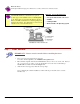
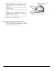
7. 8. 9. 10. 11. 12. 13. Refer to the figure at the right. Align the groove in the DaqBoard’s PCI edge-connector with the ridge of the desired PCI slot, and with the PC’s corresponding rearpanel slot. Push the board firmly into the PCI slot. The board will snap into position. Secure the board by inserting the rear-panel adapter-plate screw. Using the previous steps, install additional boards into available PCI bus-slots, if applicable to your application. Replace the computer’s cover.
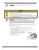
Step 3 – Configure Boards DaqBoard/500 Series Boards have no jumpers or switches to set. Configuration is performed entirely through software. Refer to the following figure and steps to complete the configuration. The numbers in the figure correspond to the numbered steps. 1. Open the “Start” menu from the Windows desktop. 2. Select “Settings.” 3. Select “Control Panel.” 4. Double-click “Daq Configuration.” This opens the Daq Configuration window. 5.
Using “Add Device” This method is for users who have accessed the Daq Configuration control panel applet, but have no DaqBoard/500 Series device icon. 1. After accessing the Daq Configuration control panel applet, click on the button (see figure, right). The Select Device Type window will appear. 2. Using the Device Type’s pull-down list, select the applicable board. In the example at the right DaqBoard/500 is selected. 3. Click the button. The board’s Properties tab will appear.
Introduction 1 The DaqBoard/500 and DaqBoard/505 have 16 single-ended or 8 differential analog inputs multiplexed to a 16-bit A/D converter with maximum throughput of 200 kHz, programmable gains of 1, 2, 4 or 8, one counter input channel, two timer output channels, and 24 lines of digital I/O. In addition, DaqBoard/500 includes two clocked DACs. The boards feature a DMA engine for optimum performance in supported Windows environments.
Block Diagram DaqBoard/500 Series Block Diagram 1-2 Introduction 947294 DaqBoard/500 Series User’s Manual
Board Features Analog I/O DaqBoard/500 Series boards support 16 single-ended or 8 differential analog inputs multiplexed to a 16-bit A/D converter. The input multiplexer is supported by a 176 element channel gain RAM which allows the board to select gain on a per channel basis and to access channels in any order. The 16-bit A/D has a maximum throughput of 200 kHz. An A/D Pacer clock is provided to allow sampling rates from 0.0009 Hz to 200 kHz. The DaqBoard/500 includes two DACs for analog output.
1-4 Introduction 947294 DaqBoard/500 Series User’s Manual
Connections and Pinouts 2 Overview …… 2-1 68-Pin SCSI Type III Connector …… 2-2 Signal Definitions …… 2-3 TB-100 Terminal Connector Option …… 2-6 External Connections …… 2-7 WARNING Always turn the computer power OFF and unplug it before connecting or disconnecting a screw terminal panel or a cable to the PCI card. Failure to do so could result in electric shock, or equipment damage. CAUTION The discharge of static electricity can damage some electronic components.
68-Pin SCSI Type III Pinout Standard 68-Pin SCSCI Type III, Socket (Female) Connector with Orb Pin 1 2 3 Signal Description / Comments Pin Signal Description / Comments DACLKIN/ CNTR1 See Pin 39 [Note 4] ADCLKIN See Pin 5 [Note 3] External DAC Clock In or Counter 1. Rising or Falling Edge Sensitive.
SCSI III Pinout Notes (Apply to the preceding table.) Note 1: AOUT 1 (DAC1) applies to DaqBoard/500 only. The clock source of the secondary DAC1 channel may be software command, DAC1 Pacer clock, or Channel 0 clock source. Likewise, the return line (ARET 1) only applies to the DaqBoard/500. Note 2: AOUT 0 (DAC0) applies to DaqBoard/500 only. The clock source of the primary DAC0 channel may be software command, DAC0 Pacer clock, or an external event (DACLKIN).
Clocks, Triggers, Counters, and Timers ADCLKIN – Uses pin #2 or pin #5. ADCLKIN is the ADC External Pacer Clock Input. This input recognizes TTL level signals and is edge sensitive. The active edge is selectable as either rising or falling. The ADCLKIN signal connection can be made at either pin #2 or pin #5, but NOT both at the same time. ADCLKOUT/TMR1 – Uses pin #37 for one of the following two functions. ADCLKOUT is the ADC’s External Clock Output.
DACLKIN/CNTR1 – Uses pin # 1 or pin # 39 for one of the following two functions. DACLKIN is the External DAC Pacer clock input. This input recognizes TTL level signals and is edge sensitive. The active edge is selectable as either rising or falling. CNTR1 is the general purpose Counter 1 clock input. This input recognizes TTL level signals and is rising edge sensitive. The input clock rate cannot exceed 500 kHz. The clock source must provide a minimum pulse width of 100 ns.
TB-100 Terminal Connector Option The TB-100 Terminal Connector option can be used to connect all signal I/O lines that are associated with a DaqBoard/500 or /505. TB-100 can connect to either board’s 68pin SCSI III connector via a 3 ft., 68-conductor cable (CA-55 or the shielded CA-56); or via a 6 ft. shield cable (CA-56-6). TB-100 Pinout The “Pin” column refers to the pin no. on the 68-Pin SCSI III Connector.
TB-100 Notes (Apply to the preceding table.) Note 1: Digital Common Pins on the SCSI III connector are: 35, 36, and 40. Note 2: Analog Common Pins on the SCSI III connector are: 24, 27, 29, 32, 59, 64, and 67. Note 3: References are not provided for DaqBoard/500 Series devices. For this reason POSREF and NEGREF are tied to the Analog Return signals. POSREF connects to ARET1 (Pin 20 on the DaqBoard) and NEGREF connects to ARET0 (Pin 54 on the DaqBoard).
Signal Types Floating Sources A Floating Source is a signal that has no connection to the building's power ground. Examples of Floating Sources are thermocouples, batteries and battery powered devices, and signals from optically isolated devices. When connecting Floating Sources to a data acquisition board, the ground reference of the signal must be tied to the analog ground (AGND) in order to establish a common reference point.
Differential (DIFF) In installations where each Ground Referenced Source signal has a local ground [signals located remote from one another] the Differential configuration must be used. Since the Differential configuration only responds to the difference in a signal between its high and low voltages, any Common Mode Voltage will be cancelled out. In addition, Differential configuration provides the best performance of the two configurations in an electrically noisy environment.
Differential for Floating Signal Sources Floating Signal Sources are typically wired to a data acquisition board in Single-Ended configuration. However, when the Floating Source signal leads pass through an electrically noisy environment, Differential configuration will give the best performance. When wiring Floating Signal sources in Differential configuration, a resistor can be connected from the low side of the sources to analog ground (AGND).
Configuration 3 Configuration through Software DaqBoard/500 Series boards have no hardware jumpers or switches. All data-acquisition settings such as analog input, data collection rates, input voltage range, and operating modes are configured through application software. A DaqView software driver provides an application level software interface to Windows NT, 2000, and XP. Software packages such as LabVIEW can also be used.
DAC Ranges The output range of the DaqBoard/500 DACs [DAC0 and DAC1] can be independently set to either ±10 V, or 0 to 10 V. The following table indicates the maximum resolution for each range. Note that resolution is not accuracy. Resolution defines the minimum definable voltage increment. Absolute DC accuracy and relative accuracy define exactly how close the actual voltage output will be to the expected output.
Software and Board Operation 4 Overview …… 4-1 Out-of-the-BoxTM Software …… 4-1 Drivers for Third-party, Icon-driven Software …… 4-2 DaqCOM Driver …… 4-2 Theory of Operation …… 4-3 Overview DaqBoard/500 Series boards have several software options. Three types of software are available: Out-of the-box graphical programs, e.g., DaqView, ViewXL, and post acquisition data analysis programs such as eZ-PostView, eZ-TimeView, and eZ-FrequencyView. drivers for third-party, icon-driven software such as LabVIEW.
Reference Notes: The software documents: DaqView, ViewXL, and Post Acquisition Data Analysis User’s Guide, are available in PDF version. During software installation, Adobe® PDF versions of user manuals will automatically install onto your hard drive as a part of product support. The default location is in the Programs group, which can be accessed from the Windows Desktop. Refer to the PDF documentation for details regarding both hardware and software.
Theory of Operation Process Definitions In order to best understand how to operate the various board functions, it is important to first understand the language that will be used to describe the board processes. The following is a list of pertinent terms and definitions used in this document. ADC Analog to Digital Converter, also referred to as A/D. This is the circuitry that samples the voltage present at one of the inputs and translates that reading to a number that is representative of the input voltage.
ADC and DAC Trigger This is the signal or impetus that initiates or terminates an Acquisition. Essentially the Trigger Starts or Stops the ADC or DAC PACER Clock. ADC Channel Configuration RAM This is the term used for the ADC’s Channel, Gain, Range, and Input Configuration lookup table. The length of this table can be anywhere from 1 element to 176 elements. When an ACQUISITION is in process, the board will sequentially go through this list to determine the channel and gain setting for the next conversion.
Starting (Triggering) an ADC Acquisition There are several methods that can be used to initiate an acquisition, all of these are achieved by triggering or gating the ADC clock as mentioned previously. Note that a trigger is an edge active event and a gate is a level controlled enable. An acquisition can be initiated via the following: o o o Software External Gate (ADTRGIN) External Trigger (ADTRGIN) ADC Software Software can be used to start and stop the on-board ADC pacer clock.
Stopping an ADC Acquisition (CLOCK) Typical ways of halting an acquisition involve use of one of the following: o o o Software External Gate (ADTRGIN) External Trigger (ADTRGIN) ADC Software The acquisition can be stopped by software control. ADC External Gate An ADC clock may also be “switched off” with the external trig/gate input (ADTRGIN). Refer to the section entitled ADC External Gate (on page 4-5 ) for additional information about this mode.
Clocking the DAC DaqBoard/500 Only DaqBoard/500 Only The DaqBoard/500 includes two DAC channels. The clock source of the primary DAC0 channel may be any of the following: o DAC0 Pacer Clock o External Event (DACLKIN). The clock source for the secondary DAC1 channel is limited to the following sources: o DAC1 Pacer Clock o Channel 0 Clock Source. DAC Software Update A single D/A conversion may be initiated by an asynchronous software update.
4-8 Software and Board Operation 988994 DaqBoard/500 Series
CE-Compliance 5 Overview ……5-1 CE Standards and Directives …… 5-1 Safety Conditions ……5-2 Emissions/Immunity Conditions ……5-2 Overview CE standards were developed by the European Union (EU) dating from 1985 and include specifications both for safety and for EMI emissions and immunity. Now, all affected products sold in EU countries must meet such standards.
For clarification, terms used in some Declarations of Conformity include: • pollution degree: any addition of foreign matter, solid, liquid or gaseous (ionized gases) that may produce a reduction of dielectric strength or surface resistivity.
Specifications 6 A digital calibration method is used for both analog-to-digital and digital-to-analog conversions. Please contact the factory should you believe your board to be in need of calibration. General Function: High speed, 16 channel multiplexed 16 Bit Analog-to-Digital converter (ADC) with programmable gain, and 24 digital I/O lines for PC compatibles.
Note: Specifications subject to change without notice. Signal to Noise and Distortion: S/(N+D) 73 dB min. @ gain = 1 Total Harmonic Distortion: 80 dB (typical) @ gain = 1, measured to 5th harmonic Full Power Bandwidth: 1 MHz Input Impedance Shunt Res.
Note: Specifications subject to change without notice. Analog Outputs DaqBoard/500 Only Channels 2; two clocked DACs designated as DAC0 and DAC1 Resolution: 16 bit Output Voltage Ranges: ±10 V, 0 to 10 V Settling time to 0.006% of FSR: 10 µsec for 20 V step Differential Linearity: ± 0.25 LSB @ 25° guaranteed monotonic Accuracy: ± 0.
Note: Specifications subject to change without notice. Counter – 1 Counter designated as CNTR1 Channels Pin Connections: SCSI-68 TB-100 (Option) 1 CNTR1 – Pin 1 or Pin 39; Shared with DACLKIN Connector – CNT1 or XDPCR; Shared with DACLKIN Input Delay: 100ns max Max. Count 65536 Max. Input Frequency: 900 Khz max Input Levels: 5 V CMOS/TTL with 4.7 K ohm pull-up resistor High Level Input Voltage: 2 V min. (High level input voltage) Low Level Input Voltage: 0.8 V max.
Glossary Acquisition A collection of scans acquired at a specified rate as controlled by the sequencer. Analog A signal of varying voltage or current that communicates data. Analog-to-Digital Converter (ADC) A circuit or device that converts analog values into digital values, such as binary bits, for use in digital computer processing. API Application Program Interface.
Differential mode voltage Differential mode voltage refers to a voltage difference between two signals that are referenced to a common point. Example: Signal 1 is +5 VDC referenced to common. Signal 2 is +6 VDC referenced to common. If the +5 VDC signal is used as the reference, the differential mode voltage is +1 VDC (+ 6 VDC - +5 VDC = +1 VDC). If the +6 VDC signal is used as the reference, the differential mode voltage is -1 VDC (+ 5 VDC - +6 VDC = -1 VDC).
Notes:
Notes:
WARRANTY/DISCLAIMER OMEGA ENGINEERING, INC. warrants this unit to be free of defects in materials and workmanship for a period of 13 months from date of purchase. OMEGA’s WARRANTY adds an additional one (1) month grace period to the normal one (1) year product warranty to cover handling and shipping time. This ensures that OMEGA’s customers receive maximum coverage on each product. If the unit malfunctions, it must be returned to the factory for evaluation.
Where Do I Find Everything I Need for Process Measurement and Control? OMEGA…Of Course! Shop online at omega.