TABLE OF CONTENTS 1. SPECIFICATIONS ...................................................................................... 1 2. PANEL FUNCTIONS ................................................................................... 2 3. OPERATING INSTRUCTION..................................................................... 4 3.1. Normal Operation................................................................................... 5 3.2. Using the Mechanical Adaptor (Option RM1502) ............................
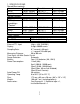
1. SPECIFICATIONS Speed (Non-contact): Range Resolution Accuracy RPM 10.00 - 99999 0.01/0.1/1 0.04% ±2 dgts rps(Hz) 0.200 - 2000.0 0.001/0.01/0.1 0.04% ±2 dgts Speed (Contact) Range Resolution Accuracy RPM / (/ 20.00 - 29999 0.01/0.1/1 0.04% ±2 dgts symoblizes "Contact" m/min 2.000 - 2999.9 0.001/0.01/0.1 0.04% ±2 dgts ft/min 6.00 - 10000 0.01/0.1/1 0.04% ±2 dgts yard/min 4.00 - 3000 0.01/0.1/1 0.04% ±2 dgts Event Counter: Range Max. Input Frequency 0 - 99999 10KHz.
2.
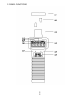
2.1. Reflecting tape Attach a reflecting tape to the surface of the unit to be measured 2.2. Reflecting signal light beam It is recommenced that the reflecting surface is perpendicular to the emitting/receiving unit for best measurement. 2.3. Emitting/Receiving Unit The red light emits from the left side of the tachometer. And a receiving sensor is installed in the right side to receive light signal from the reflecting surface. 2.4.
2.10. Start Measurement Symbol 2.11.
3.
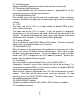
3.1. Normal Operation a. Install four 1.5V AA size batteries. b. Cut off a piece of reflective tape of size 1.0 cm x 1.4 cm (optimal size) c. Wipe off oil or stains from the surface where reflective tape will be adhered. d. Stick the self-adhesive reflective tape on the object whose rotational speed is to be measured. The reflective tape should be attached as close to the outer edge of the object to be measured as possible. e. Press the START button to turn on tachometer. f.
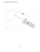
3.2. Using the Mechanical Adaptor (Option RM1502) a. Select proper rubber head. b. Attach the mechanical adaptor to the unit.and fasten the screw. c. Press the unit button (left button) to select RPM / ( instead of RPM only). The auxiliary LED will be turned on while the main LED will be turned off. d. Press against the shaft of the object to be measured. e. Do not press against the shaft too hard to avoid hazard. WARNING: Do not exceed the speed limit of 29999 rpm when using mechanical adaptor.
3.3. Measurement of Surface Speed(m/min, ft/min, or yd/min) a. Attach the mechanical adaptor (option RM-1502) to the unit. b. Press the unit button to select desired unit. The auxiliary LED will be turned on while the main LED will be turned off. c. Slightly touch against the surface to be measured.
3.4. Use as an Event Counter with External Light Source a. Press the unit button several times to select the unit of "No. O" (counts). The "O" symbol is used to instruct users that external light source is required. b. When the symbol "No. O" appears, the tachometer reset the upper clock to 00:00 and start counting the pulses it detects. (Auto-poweroff is automatically disabled) c. To stop counting, press the START button once. d. To reset counts to zero, press the function(right) button. 3.5.
3.6. External Signal(TTL) Input (RM1501) Instead of receiving signal from light source, users can input external TTL signal (High: > 4.5V, Low: 0V) through pin 8 of RS232C connector with pin 5 as signal ground. NOTE: It is strongly recommended that the emiting/receiving unit be covered to avoid undesired light signal coming in. 3.7. Digital Pulse Signal Output (RM1501) Users can output digital pulse signal through pin 8 of RS232C connector with pin 5 as signal ground to oscilloscope.
3.8. Measuring Slow Rotating Objects If the rotating speed of the object which you are measuring is very slow, it is recommended that you use a tripod to hold the tachometer in place and use multiple pieces of tape for more accurate result. If multiple pieces of tape are used, each piece of tape should be located at a equal distance to each other on the object. Any number of pieces of tape are acceptable. But you need to divide the reading by the number of pieces to obtain the correct result.
seconds, and the max/min/ave symbols will disappear in LCD. 3.10. Turning On/Off Tachometer Press any button will turn on the power of tachometer. To turn off the power of tachometer, press and hold the START button until word "OFF" is displayed in LCD. Then release the START button. 3.11. Disable Auto-Power-Off Function If tachometer is in auto-power-off mode, only the minutes will be displayed. And tachometer will be turned off in 30 minutes.
3.12. REPLACING THE BATTERIES a. When the symbol (low battery) appears in the LCD, it is time to replace the batteries. b. Remove the screw of the battery cover and remove the battery cover. c Replace the old batteries with 4 new batteries. Do not mix different type of batteries together. d. Replace the battery cover and fasten the screw.
4. Protocol of RS-232C Serial Interface (RM-1501) Ten bytes are sent out through RS-232C connector to PC. The definitions of each byte are as followings: Byte 1: Leading byte 0x0D Byte 2: Decimal point of LCD display bit0: dp1 (0000.0), if 1 bit1: dp2 (000.00), if 1 bit2: dp3 (00.000), if 1 Byte 3: Flags for current status bit0: low battery, if 1 bit1: Max. value overflow, if 1 bit2: Counter overflow, if 1 bit3: Auto-power-off disable, if 1 bit4: Min. value overflow, if 1 bit5: Ave.
5. Installation of WindowTM Application Software (RM-1501) 5.1. For Windows 3.1 A. Start MicrosoftTM WindowsTM B. Insert disk in drive A (or B) C. From Program Manager, select File menu and choose Run D. Type a:\setup (or b:\setup) and press Enter key 5.2. For Windows 95 A. Start WindowsTM 95 B. Insert disk in drive A (or B) C. Press START button, then select Run D.
6. Description of Windows TM Application Program (RM-1501) Main Window: When the program is executed, the program automatically search for connected tachometer or available serial port. If no serial port is available, then a message of "No communication port" will be displayed, and the program exits . Once communication port is setup, a main window will be displayed on the screen as below: Sample: Option: Unit: Value: Range: Sampling time. Display option of anemometer.
VIEW FILE: If the View option under FILE in the Main Window is selected, a view window will be shown as above, and the users can review your ASCII data file. If a printer is connected to the PC, users can print out content selectively. File:Open users data file by selecting this menu. Users will be asked to enter file name. After the name being entered, program will read in one block of data. Number of records in one block depends on the memory size of PC. The bigger memory, the more records in one block.
Selected: Indicate the current record number being selected. DISPLAY: DISPLAY menu has four options: DIGITAL, ANALOG, LIST, and GRAPHIC. DIGITAL: If this option is selected or CTRL+D is pressed, a window, which emulates multimeter's LCD display, shall appears on the screen.
If this option is selected or CTRL+A is pressed, a window, which emulates an analog meter, shall appear on the screen. LIST: If this option is selected or CTRL+L is pressed, a window, which lists the date, function, range, and value every sampling, shall appear on the screen. GRAPHIC: If this option is selected or CTRL+G is pressed, a window, which emulates strip chart recorder, shall appear on the screen. The graphic window has two menu, PRINT and SCALE.
the minimum and maximum value for the Y (vertical) axis. Option: If you select Option, a pull down menu will show three options: Sample Rate, Baud Rate. Upper Limit: Enter upper limit. If upper limit is exceeded, a OVER message will be displayed in screen. Lower Limit: Enter lower limit. If displayed value is less than lower limit, a UNDER message will be displayed in screen. Graphic Mode: Select way of display in the graphic windows. Dot or BAR.
21 21
22 22
23 23