User’s Guide Shop online at omega.com e-mail: info@omega.com For latest product manuals: omegamanual.
OMEGAnet ® Online Service www.omega.com Internet e-mail info@omega.com Servicing North America: USA: ISO 9001 Certified Canada: One Omega Drive, Box 4047 Stamford CT 06907-0047 Tel: (203) 359-1660 e-mail: info@omega.com 976 Bergar Laval (Quebec) H7L 5A1, Canada Tel: (514) 856-6928 e-mail: info@omega.
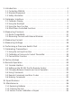
1. Introduction . . . . . . . . . . . . . . . . . . . . . . . . . . . . . . . . . . . . . . . . . . . .1 1.1 Contacting OMEGA . . . . . . . . . . . . . . . . . . . . . . . . . . . . . . . . . . . . . . . .1 1.2 Standard Equipment . . . . . . . . . . . . . . . . . . . . . . . . . . . . . . . . . . . . . . .1 1.3 Safety Information . . . . . . . . . . . . . . . . . . . . . . . . . . . . . . . . . . . . . . . . .1 2. Calibrator Interface . . . . . . . . . . . . . . . . . . . . . . . . . . . . . . . . . . . . .
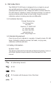
1. Introduction The OMEGA PCL340 Series is designed to be a simple to use yet very versatile pressure calibrator. Its internal pressure sensor combined with inputs for mA, voltage and switch contacts allow the PCL340 Series to calibrate a variety of pressure devices. An external pressure module option allows an even wider range of pressure calibration options including absolute and differential. 1.
Symbol Description Double Insulated Electric Shock Fuse PE Ground Hot Surface (Burn Hazard) Read the User’s Manual (Important Information) Off On The following definitions apply to the terms “Warning” and “Caution”. • “Warning” identifies conditions and actions that may pose hazards to the user. • “Caution” identifies conditions and actions that may damage the instrument being used. Use the calibrator only as specified in this manual, otherwise injury and damage to the calibrator may occur.
• Select the proper function and range for your measurement. • Make sure the battery cover is closed and latched before you operate the calibrator. • Remove test leads from the calibrator before you open the battery door. • Inspect the test leads for damaged insulation or exposed metal. Check test leads continuity. Replace damaged test leads before you use the calibrator. • When using the probes, keep your fingers away from the probe contacts. Keep your fingers behind the finger guards on the probes.
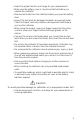
2. Calibrator Interface Figure 1 shows the location of the process measurement inputs, while table 1 describes their use. Side View Figure 1 Process Measurement Inputs Table 1 Process Measurement Inputs No. Name Description 1, 2 Input Terminals These terminals are used to measure current, voltage and a contact closure for switch test.
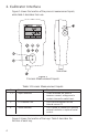
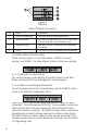
Figure 2 Keypad Table 2 Key Functions No. Name Description 1 Function Keys These keys are used in various ways, primarily to configure the calibrator 2 ON/OFF Key This key is used to turn the calibrator on and off 3 ZERO Key This key is used to zero pressure measurements 4 Backlight Key This key is used to turn the backlight on and off 2.1 Calibrator Display The Calibrator Display consists of two regions: The menu bar (located along the bottom of the screen) is used to access a menu system.
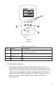
Figure 3 Display Table 3 Display Functions No. Name Description 1 Primary Parameters Indicates what is being measured. 2 Span Indicator Indicates the percent of the 4 to 20 mA span. (For mA and mA Loop functions only) 3 Pressure Units Indicates one of 17 pressure units available for display. 4 Units Indicates the unit of measure for the display. 2.1.1 Main Menu Functionality There are three options on the Main Menu, CONFIG, {current display} and MORE.
With a single display the following modes are available: P[1] = Pressure on left side sensor. [EXT] = Pressure with external pressure module. P[1] ST = Switch Test with left side sensor. [EXT] ST = Switch Test with external pressure module. mA = Milliamps measure without loop power. mA LOOP = Milliamps measure with loop power. VOLTS = Voltage Measure. The following table shows which functions are available concurrently.
Figure 4 Menu Map 8
2.2 Using the Backlight The backlight is controlled by the dedicated backlight key. It toggles on and off when the key is pressed; this is one of the few functions that cannot be controlled by the serial interface. 2.3 Using the Zero Function When the ZERO_KEY is pressed, the calibrator will zero the current display if a pressure mode is selected, and the pressure is within the zero limit. 2.3.
2.4.1 Setting the Contrast From the Contrast Main Menu choose the CONTRAST option to access the Contrast Adjustment Menu. Use the arrow keys to adjust the display contrast to the desired level and then use the CONTRAST DONE option to return home. 2.4.2 Locking and Unlocking Configurations Use the LOCK CFG or UNLOCK CFG option of the Configuration Lock Menu to lock or unlock the display configuration.
2.4.4 Setting AutoShut-off Parameters The calibrator can be set to automatically shut-off after a selected number of minutes; this function can also be disabled. To set the auto shut off parameters select the AUTO OFF option on the Auto Shut Off Main Menu. Use the arrow keys to select the number of minutes before the calibrator turns off or disable auto shut-off by scrolling all the way down. Use the AUTO OFF DONE option to set the parameters and return home.
configurations of the other currently active displays, if the configurations are in conflict the recalled display’s configuration is modified to avoid the conflict. If all three displays are deactivated the LOWER display will come on automatically 3. Measuring Pressure To measure pressure, connect the calibrator using an appropriate fitting. Choose a pressure setting for the display being used. The calibrator is equipped with one internal sensor and many optional external Pressure Modules are available.
including gauge, vacuum, differential and absolute. The modules work seamlessly with the calibrator. Simply plug them into the interface and select [EXT] (external sensor). Since the interface between the calibrator and the module is digital all the accuracy and display resolution is derived from the module. Figure 6 4. Measuring Current To measure current use the input terminals in the front of the calibrator. Select the mA function on one of the displays.
Figure 7 5. Measuring Voltage To measure voltage use the input terminals in the front of the calibrator. Select the Volts function on one of the displays. The calibrator can measure up to 30V.
6. Performing a Pressure Switch Test Pressure switch under test Figure 10 To perform a switch test, follow these steps: 1. Change the setup to Setup 4 (default switch test). Setup 4: The upper display is set to [P1] ST, all other displays are off. Important NOTE: The pressure Switch Test can be performed with the following functions[P1] ST, or EXT ST. 2. Connect the calibrator to the switch using the pressure switch terminals. The polarity of the terminals does not matter.
5. Apply pressure with the pump slowly until the switch opens. Important NOTE: In the switch test mode the display update rate is increased to help capture changing pressure inputs. Even with this enhanced sample rate pressurizing the device under test should be done slowly to ensure accurate readings. 6. Once the switch is open, “OPEN” will be displayed, bleed the pump slowly until the pressure switch closes. 7.
9. Press the “NEW TEST” option to clear the data and perform another test. 10. Press the “DONE” option to end the test and return to the standard pressure setting. Example: [P1] ST will return to [P1]. Important NOTE: The previous example uses a normally closed switch. The basic procedure is still the same for a normally open switch, the display will just read “OPEN” instead of “CLOSE”. 7. Calibrating Transmitters 7.
7.2 Calibrating a Pressure-to-Current Transmitter To calibrate a pressure-to-current transmitter (P/I), perform the following steps: 1. Connect the calibrator and the pump to the transmitter. 2. Apply pressure with the pump. 3. Measure the current output of the transmitter. 4. Ensure the reading is correct. If not, adjust the transmitter as necessary. Figure 11. 7.3 Percent Error Function The calibrator features a unique function which can calculate pressure vs.
Figure 12. Example: Suppose a pressure transmitter under test is 30 psi (2 Bar) Full Scale and outputs a corresponding 4 to 20 mA signal. The user can program in a 0 to 30 psi pressure span into the calibrator and the calibrator will calculate and display the deviation or % Error from the expected 4 to 20 mA output. This eliminates the need for manual calculations and also helps if it becomes difficult to set an exact pressure with an external pump. To use the %ERROR function proceed as follows: 1.
4. LOOP POWER can be toggled on/off, select NEXT when done. 5. Use SELECT to toggle through the UNIT options, and select NEXT to move on. 6. Use the ↑ and ↓ arrows to set the 100% point of the desired pressure range, select DONE SET when finished. 7. Again, use the arrows to set 0% point and select DONE SET when finished and the %ERROR mode will be ready to use.
Note: The 0% and 100% point will be saved in non-volatile memory until they are changed again by the user for the internal sensors, and external pressure modules. When using an external module the 0% and 100% are set to low and full scale of the module until the user changes it, or if it was previously saved. 8. Factory Setups The Calibrator is loaded with five factory setups. These setups are shown below. Setup 1: The upper display is set to [P1] mode and the middle is set to mA, lower is off.
Setup 3: The upper display is set to [P1] mode and the middle is set to [VOLTS] mode, lower is off. Setup 4: The upper display is set to [P1], the lower display is set to [EXT]. Setup 5: The upper display is set to [P1], and the lower display is set to mA Loop.
9. Remote Operation 9.1 Remote Interface The calibrator can be remotely controlled using a PC terminal, or by a computer program running the calibrator in an automated system. It uses an RS-232 serial port connection for remote operation. NOTE: To use the remote control option a custom RS-232 cable must be purchased from OMEGA (LEM232). To contact OMEGA refer to Section 1.1 of this manual.
To set up remote operation of the calibrator on the Windows Hyper Terminal, connected to a COM port on the PC as in Figure 23, use the following procedure: 1. Start Hyper Terminal (located in Accessories/Communications of the Windows Start menu) 2. Select New Connection. 3. For Name enter PCL340. Select the serial port that the calibrator is connected to. 4. Enter the above information for port settings. 5.
The calibrator may be controlled using commands and queries. All commands may be entered using upper or lower case. The commands are divided into the following categories: Calibrator Commands Only the calibrator uses these commands. For example VAL? asks for the values displayed on the calibrator display. Common Commands Standard commands used by most devices. These commands always begin with an “*”. For example *IDN? tells the calibrator to return its identification.
Integer For most computers and controllers they are decimal numbers ranging from -32768 to 32768. For example: FAULT? could return 110 Refer to the Error Codes table (Table 8) for more information on error codes. Floating Floating numbers have up to 15 significant figures and exponents. For example: ZERO_MEAS returns 1.210000E-2, PSI Character Response Data (CRD) Data returned as keywords. For example: PRES_UNIT? returns PSI, NONE, NONE Indefinite ASCII (IAD) Any ASCII characters followed by a terminator.
9.5 Remote Commands and Error Codes The following tables list all commands, and their descriptions, that are accepted by the calibrator. Table 5: Common Commands Command Description *CLS (Clear status.) Clears the error queue. *IDN? Identification query. Returns the manufacturer, model number, and firmware revision level of the Calibrator. *RST Resets the calibrator to the power up state. Table 6: Calibrator Commands Command Description DAMP Turns Damp on or off.
ST_START Starts a switch test ST_OPEN? Returns pressure value at which the switch opened ST_CLOSE? Returns pressure value at which the switch closed ST_DEAD? Returns pressure value of the deadband of the switch VAL? Returns the measured values ZERO_MEAS Zeros the pressure module ZERO_MEAS? Returns the zero offset of the pressure module Table 7: Parameter units Units Meaning MA milliamps of current V Voltage in volts PSI Pressure in pounds per square-inch INH2O4C Pressure in inches of
Table 8: Error Codes Error Number Error Description 100 A non-numeric entry was received where it should be a numeric entry 101 Too many digits entered 102 Invalid units or parameter value received 103 Entry is above the upper limit of the allowable range 104 Entry is below the lower limit of the allowable range 105 A required command parameter was missing 106 An invalid command parameter was received 107 Pressure not selected 108 Invalid sensor type 109 Pressure module not connected 1
9.6.2 Calibrator Commands DAMP Turns the dampening function on or off. For example: If you send DAMP ON this will turn the dampening function on. DAMP? Returns the current state of the dampening function. For example: If you send DAMP? It will return ON if the dampening function is on. DISPLAY Turns the indicated display on or off. For example: If you send DISPLAY LOWER, ON this will turn the lower display on. DISPLAY? Returns the current state of the each of the displays.
ERROR _LOOP Turns loop power on or off in percent error mode. For example: To set loop power on send ERROR_LOOP ON. ERROR _LOOP? Returns the current state of loop power in percent error mode. For example: If you send ERROR_LOOP? It will return ON if loop power is on in error mode. ERROR_ MODE Turns percent error mode on and off. For example: To turn on percent error mode send ERROR_MODE ON. ERROR _ MODE? Returns the current state of percent error mode.
FUNC Sets the display indicated in argument one to the function indicated in argument 2. For example: To set the lower display to P1 Pressure mode send FUNC LOWER,P1. FUNC? Returns the current mode of all displays. For example if the calibrator is set to [P1] ST on the upper display, [P1] on the middle, and the lower display is off, FUNC? Would return: ST_P1,P1,NONE HI_ERR Sets the 100% point for the percent error mode calculation in the current engineering units.
LO_ERR Sets the 0% point for the percent error mode calculation in the current engineering units. For example: To set the 0% point to 20 psi send LO_ERR 20. LO_ERR? Returns the 0% point for the percent error mode calculation. For example: If the 0% point is set to 20 psi, LO_ERR? would return 2.000000E+01, PSI . PRES_UNIT Used to set the pressure unit for the indicated display For example: To set the pressure unit to psi on the lower display send PRES_UNIT LOWER, PSI.
PRES_UNIT? Returns the pressure unit used when measuring pressure for each of the 3 displays. REMOTE Puts the calibrator in remote mode. From the remote mode the user can still use the keypad to get back to local unless the command LOCKOUT was entered before REMOTE. Than the keypad is totally locked out, and the user has to send the LOCAL command to get back to local operation. ST_START Starts a switch test. ST_CLOSE? Returns the pressure that the switch closed at in the current pressure units.
10. Specifications (18 °C to 28 °C unless otherwise noted.) General Instrument Setup Recall 5; last used on power-up Environmental Operating Temperature Storage Temperature -10 °C to +50 °C -20 °C to +60 °C Power Requirements Battery Battery Life 6.0 VDC Four (4) standard AA cells > 25 hours, typical usage Physical Dimensions Weight 8.3” H x 3.9” W x 1.8” D (21.082 x 9.906 x 4.572 cm) 1 lb. 4 oz. (0.
11. Maintenance 11.1 Replacing Batteries Replace batteries as soon as the battery indicator turns on to avoid false measurements. If the batteries discharge too deeply the PCL340 will automatically shut down to avoid battery leakage. Note: Use only AA size alkaline batteries or optional rechargeable battery pack. 11.2 Cleaning the Unit Warning To avoid personal injury or damage to the calibrator, use only the specified replacement parts and do not allow water into the case.
WARRANTY/DISCLAIMER OMEGA ENGINEERING, INC. warrants this unit to be free of defects in materials and workmanship for a period of 13 months from date of purchase. OMEGA’s Warranty adds an additional one (1) month grace period to the normal one (1) year product warranty to cover handling and shipping time. This ensures that OMEGA’s customers receive maximum coverage on each product. If the unit malfunctions, it must be returned to the factory for evaluation.
Where Do I Find Everything I Need for Process Measurement and Control? OMEGA…Of Course! Shop online at www.omega.