User’s Guide ™ ® http://www.omega.com e-mail: info@omega.
TABLE OF CONTENTS SAFETY CONSIDERATIONS ......................................................................................... iii 1.0 GENERAL INFORMATION ........................................................................................ 1 2.0 SPECIFICATIONS..................................................................................................... 1 2.1 Analog Input ......................................................................................................... 1 2.
LIST OF FIGURES: Figure 3.1 Figure 3.2 Figure 4.1 Figure 4.2 Figure 5.1 Figure 5.2 Figure 5.3 Figure 7.1 Figure 8.1 DIN Case Dimensions .................................................................................. 4 Exploded View.............................................................................................. 5 Side View of Transformer ............................................................................. 6 Rear Terminal Hookups .....................................................
SAFETY CONSIDERATIONS This device is marked with the international Caution symbol. It is important to read this manual before installing or commissioning this device as it contains important information relating to Safety and EMC (Electromagnetic Compatibility). Unpacking & Inspection Unpack the instrument and inspect for obvious shipping damage. Do not attempt to operate the unit if damage is found.
1.0 GENERAL INFORMATION This voltmeter is a 4 1/2 digit panel meter for applications which require a compact, quality DC voltmeter. This model uses dual-slope conversion. Additionally, it provides automatic zeroing before each reading and does so with a minimum of parts for increased reliability. The voltmeter has a resolution of 1 part in ±19999 counts.
2.4 ACCURACY AT 25°C Maximum error Span tempco Step response Warm-up to rated accuracy ±0.01% of reading ±2 counts ±0.01% of reading/°C 1 second 10 minutes 2.5 DIGITAL INPUTS Positive true referenced to DIG GND Input HOLD LAMP TEST DISPLAY BLANKING 2.6 Logical 0 0 to 0.8 V 0 to 0.6 V 0 to 0.6 V Overrange indication Dual-slope, average-value 100 milliseconds 2.5/second 7 segments, 14.2 mm (0.56 in) height -1.8.8.8.
2.10 MECHANICAL Bezel Depth behind bezel (with connector) Panel cutout Weight Case material D1 connector option (non-CE) D4 connector option (CE) 96 x 48 x 5.1 mm (3.78 x 1.89 x 0.20 in) 104 mm (4.09 in) 92 x 45 mm (3.62 x 1.77 in) 400 g (14 oz) 94V-0 UL-rated polycarbonate PCB edge connector with a double row of 18-pins, 3.96 mm (0.156 in) spacing between pins Barrier terminal strip with six #6 screw connections for signal and power (removes these inputs from D1) 3.
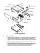
TAB I.D. LABEL CASE, TOP SLIDE SCREW (2) SLIDE CLAMP (2) PARALLEL BCD OUTPUT BOARD (F2N OPTION) SLIDE RETAINER (2) TERMINAL BLOCK COVER SIGNAL INPUT POWER INPUT LENS MAIN BOARD SPAN ADJUST CASE, BOTTOM Figure 3.2 Exploded View 3.2 PANEL MOUNTING 1. Remove main board connector J1, if installed. Loosen the two clamp screws (with a #8 Phillips screwdriver) on the rear of case and rotate the slide clamps. Push the two slide retainers toward the rear of the unit and remove them. 2.
4.0 POWER AND SIGNAL AC versions of the voltmeter are factory-set for 115 Vac in the USA and 230 Vac in Europe (using C1 option) ±15% operation. DC versions are preset for 9-32 Vdc or 26-56 Vdc operation. It is not possible to change the meter from 9-32 Vdc to 26-56 Vdc or vice versa. Different static inverters are installed by the factory. Refer to Safety Considerations prior to connecting power. 4.1 CHANGING OPERATING VOLTAGE Remove power lines from the meter, then remove the meter from the case.
(D4) (D1) Figure 4.
4.3 MAIN BOARD PIN ASSIGNMENTS (J1 Card Edge) Left to right, looking at rear of case P1 Connection A 1 B 2 C 3 D 4 E 5 F 6 H 7 J 8 K 9 L 10 M 11 N 12 P 13 R 14 S 15 T 16 U 17 V 18 Standard Spare (E16) No connection No connection Spare (E18) Spare (E19) No connection No connection No connection Spare (E43) No connection 1999.9 (DP4) Spare (E24) 199.99 (DP3) Spare (E23) 19.999 (DP2) Spare (E22) 1.9999 (DP1) Spare (E25) Decimal point select Spare (E26) Spare (E27) –4.6 Vdc power output Spare (E29) +4.
4.4 SIGNAL INPUTS RATIO: The reference input allows an external voltage to be used as the reference source for conversion. In this mode, the meter reads the ratio of the signal voltage to the reference voltage rather than the true value of the input. Reading in Counts = Signal Voltage x 10000 Reference Voltage On the 20 V and 200 V ranges, the signal voltage must be scaled by 1/10 and 1/100, respectively. For all ranges, the standard reference input impedance ratio is 80 ohm.
5.0 CONFIGURATION Select the desired configurations from the following charts. Install jumpers and open/close solder switches as indicated. Remove all push-on jumpers not used. 5.1 DECIMAL POINT SELECTION Figure 5.1 Display Board Jumper Locations Decimal Point S1 Alternate decimal point configuration using main board connector J1. 1.9999 19.999 199.99 1999.
5.2 VOLTAGE RANGE SELECTION Figure 5.2 Main Board Jumper Locations Input Configuration 2 Vdc 20 Vdc 200 Vdc Solder Switches* Open Close J, L H, I, K J, L H, I, K J, L H, I, K Push-on Jumpers S2 S4 A B A C Wire Jumper W10 Install Remove Remove *Refer to Figure 5.3. S3-A is used for signal connections. Refer to Section 4 for more information.
Figure 5.3 Solder Switch Locations Solder switch F is used for reference input impedance ratio. Refer to Section 4 for more information. 6.0 CALIBRATION This unit was factory-calibrated with a precision voltage source. Frequent calibration is not necessary due to the stability and internal accuracy. If calibration is needed, use the following procedure. 1. Remove the front lens. Insert a blade screwdriver under the notch at the bottom of the lens and gently pry it off. 2.
7.0 DRAWINGS Figure 7.
8.0 DUAL-SLOPE CONVERSION At the beginning of a conversion, the voltage across Cint is zero. The signal is then applied to the integrator and the voltage across Cint rises by the formula: T1 ECint = Esig RintCint At the end of a fixed period of 10000 counts, T1, the counters are reset to 00000. The signal input is turned off and a stable reference voltage of the opposite polarity is now applied to the input.
NOTES ______________________________________________________________________________ ______________________________________________________________________________ ______________________________________________________________________________ ______________________________________________________________________________ ______________________________________________________________________________ ______________________________________________________________________________ ________________________________
NOTES ______________________________________________________________________________ ______________________________________________________________________________ ______________________________________________________________________________ ______________________________________________________________________________ ______________________________________________________________________________ ______________________________________________________________________________ ________________________________
NOTES ______________________________________________________________________________ ______________________________________________________________________________ ______________________________________________________________________________ ______________________________________________________________________________ ______________________________________________________________________________ ______________________________________________________________________________ ________________________________
WARRANTY/DISCLAIMER OMEGA ENGINEERING, INC. warrants this unit to be free of defects in materials and workmanship for a period of one (1) year from the date of purchase. In addition to OMEGA’s standard warranty period, OMEGA Engineering will extend the warranty period for one (1) additional year if the warranty card enclosed with each instrument is returned to OMEGA. If the unit malfunctions, it must be returned to the factory for evaluation.
Where Do I Find Everything I Need for Process Measurement and Control? OMEGA…Of Course! Shop on line at omega.