User’s Guide Shop online at omega.com e-mail: info@omega.com For latest product manuals: omegamanual.
OMEGAnet ® Online Service omega.com Internet e-mail info@omega.com Servicing North America: U.S.A.: ISO 9001 Certified Canada: One Omega Drive, P.O. Box 4047 Stamford, CT 06907-0047 TEL: (203) 359-1660 e-mail: info@omega.com 976 Bergar Laval (Quebec) H7L 5A1, Canada TEL: (514) 856-6928 e-mail: info@omega.ca FAX: (203) 359-7700 FAX: (514) 856-6886 For immediate technical or application assistance: U.S.A.
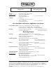
Foreword Thank you for purchasing the OMEGA RD100B Recorder. This manual describes the functions (excluding the communication functions), installation and wiring procedures, operating procedures, and lists the handling precautions of the RD100B Recorder. To ensure correct use, please read this manual thoroughly before beginning operation. The following three manuals including this manual are available for the RD100B Recorder. • Electronic Manuals Provided on the Accompanying CD-ROM Manual Title Manual No.
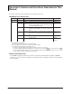
Recorder’s Version and Functions Described in This Manual The contents of this manual corresponds to the recorder with version 1.11. RD100B Versions and Functions Version Suffix Code 1.02 or earlier – 1.11 – – – – /C3 /C7 • Added or Modified Functions – (Added) The printout/display format of the date can be changed.
Safety Precautions The general safety precautions described here must be observed during all phases of operation. Safety Standards and EMC Standards This recorder conforms to IEC safety class I (provided with terminal for protective grounding), Installation Category II, Measurement Category II (CAT II), and EN61326-1 (EMC standard), class A (use in a commercial, industrial, or business environment). This recorder is designed for indoor use. About This Manual • This manual should be read by the end user.
Safety Precautions WARNING • Power Supply Ensure that the source voltage matches the voltage of the power supply before turning ON the power. • Protective Grounding Make sure to connect the protective grounding to prevent electric shock before turning ON the power. • Necessity of Protective Grounding Never cut off the internal or external protective earth wire or disconnect the wiring of the protective earth terminal.
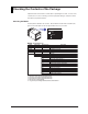
Checking the Contents of the Package Unpack the box and check the contents before operating the recorder. If some of the contents are not correct or missing or if there is physical damage, contact the dealer from which you purchased them. Checking the Model A name plate is affixed to the recorder. Check that the model name and suffix code given on the name plate on the rear panel match those on your order. RD100B RECORDER R C US LR99988 N200 MODEL SUFFIX STYLE SUPPLY FREQUENCY NO.
Checking the Contents of the Package Standard Accessories The standard accessories below are supplied with the recorder. Check that all contents are present and undamaged.
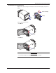
Checking the Contents of the Package Removing the Packing Materials Open the door, put your finger on the tab at the lower left of the display, and open the display. Tab on the display Open Display Open Remove all packing materials. • Pen Model Hinge • Dot Model Hinge CAUTION To protect the hinges, do not apply vertical force on the display.
How to Use This Manual This user’s guide consists of the following sections. For details on communication functions, see the RD100B/RD1800B Communication Interface User’s Manual on the CD-ROM. Chapter Title and Description 1 Functional Description Describes the functions of the RD100B Recorder. Refer to this chapter when you are unsure of the details of the function that you are operating. 2 Before Using the Recorder Describes the installation and wiring procedures.
How to Use This Manual 1 Conventions Used in This Manual Unit K ........ Denotes 1024. Example: 768 KB (file size) k ........ Denotes 1000. 2 Safety Markings The following markings are used in this manual. 3 Improper handling or use can lead to injury to the user or damage to the instrument. This symbol appears on the instrument to indicate that the user must refer to the user’s 4 manual for special instructions.
Contents Foreword ......................................................................................................................................... i Recorder’s Version and Functions Described in This Manual ......................................................... ii Safety Precautions ......................................................................................................................... iii Checking the Contents of the Package .....................................................
Contents 5.4 5.5 Changing the Chart Speed ............................................................................................ 5-13 Setting the Date/Time .................................................................................................... 5-14 Chapter 6 Setup Operations for Convenient Functions (Setting Mode) 6.1 6.2 6.3 6.4 6.5 6.6 6.7 6.8 6.9 6.10 6.11 6.12 6.13 Setting the Trend Recording Interval (Dot Model). ...........................................................
Contents 9.8 9.9 9.10 9.11 9.12 9.13 9.14 9.15 9.16 9.17 Setting the Partial Expanded Recording ........................................................................ 9-16 Turning Trend Recording (Dot Model) and Periodic Printout ON/OFF for Each Channel ................................................................................................ 9-17 Setting Tags on Channels ..............................................................................................
Chapter 1 Functional Description 1.1 1 Overview of the Recorder RD100B Recorder Recording example (dot model) Alarms For each channel, various alarms such as high limit alarm and low limit alarm can be assigned to monitor the measured values. Alarm output relays can be used to output contact signals when alarms occur (/A1, /A2, and /A3 options). Recording The measured results are recorded with pens or dots on a chart paper (trend recording).
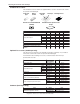
1.2 Measuring Input Section Input Section Number of Measurement Channels and Scan Interval The recorder samples the input signals on the measurement channels at the scan interval to obtain the measured values. Model Number of Channels Scan Interval 1-pen model 2-pen model 3-pen model 4-pen model Dot model 1 2 3 4 6 125 ms 125 ms 125 ms 125 ms 1s (However, the scan interval is 2.5 s when the integration time of the A/D converter is 100 ms.
1.2 Measuring Input Section Channel set to delta computation Input value Measured value – Measured value on the reference channel DC voltage Note A channel whose input type is set to DC voltage, TC, or RTD can be designated as a reference channel. However, channels set to scaling or square root computation cannot be designated. • Scaling The input values are scaled to values in the appropriate unit to be used as measured values. Input value 10 V Measured value 300.0°C 0V −100.
1.2 Measuring Input Section Bias A given value (bias value) is added to the input value and used as the measured value of that channel. Biased channel + Input value Measured value + Bias value Setting the bias: Section 7.15 and 6.12 Burnout Detection of Thermocouples This function makes the recording go off the scale to the right or left when the thermocouple burns out while measuring temperature with a thermocouple. This function can also be used on 1-5V.
1.2 Measuring Input Section 1 Noise Elimination from Input Signals Filter result (output for a step input) Input 63.2% of the output value Output response curve (when using the filter) 2, 5, 10 s (time constant, the time it takes to reach 63.2% of the output value) • Moving Average (Dot Model) The average value of the m most recent values acquired at the scan interval is used as the measured value of the channel. The number of moving-averaged data points (m) can be set in the range 2 to 16.
1.2 Measuring Input Section Integration Time of the A/D Converter The recorder uses an A/D converter to convert the sampled analog signal to a digital signal. By setting the integration time of the A/D converter to match the time period corresponding to one cycle of the power supply or an integer multiple of one cycle, the power supply frequency noise can be effectively suppressed. The integration time of the A/D converter is selected according to the model from the table below.
1.3 1 Alarms Alarm Types Number of Alarm Point Marks Up to four alarms can be set for each channel. Alarm Conditions The eight conditions below are available. The character inside the parentheses is the symbol used to denote each alarm on the recorder. • High Limit Alarm (H) An alarm occurs when the input value exceeds the alarm value. • Low Limit Alarm (L) An alarm occurs when the input value falls below the alarm value.
1.3 Alarms • Delay High Limit Alarm (T) An alarm occurs when the measured value remains above the alarm value for a specified time period (alarm delay period). • Delay Low Limit Alarm (t) An alarm occurs when the measured value remains below the alarm value for a specified time period (alarm delay period).
1.3 Alarms 1 Alarm Indication Non-hold Hold Alarm ACK Alarm occurrence Alarm Alarm ACK or Alarm release Blinking Blinking ON Alarm indication OFF or OFF ON OFF Setting the non-hold/hold operation of the alarm indicator: Section 7.1 Alarm Recording The alarm occurrence/release can be recorded on the chart paper. See section 1.4. Alarm Output Relay (/A1, /A2, and /A3 Options) Contact signals can be generated from alarm output relays when alarms occur.
1.3 Alarms Reflash Alarm When multiple alarms are assigned to one alarm output relay, this function notifies the occurrence of subsequent alarms after the relay is activated by the first alarm. When subsequent alarms occur, the output relay is released temporarily (approximately 500 ms). The reflash alarm function is set to three output relays (I01, I02, and I03 (I01 and I02 for the /A1 option)). By default, the reflash alarm is disabled.
1.3 Alarms Channel 01 Alarm Channel 02 AND Alarm output relay OR The alarm output relays assigned to AND operation are specified as follows: “I01 (first relay) to Ixx (where xx is the relay number).” The default setting is “no AND relay.” Note • • If the reflash alarm is enabled, I01 to I03 are fixed to OR operation. Specifying AND produces no effect. If diagnosis output is enabled, I01 is set to diagnosis output. Specifying AND produces no effect.
1.3 Alarms Non-Hold/Hold Operation of Alarm Output Relays The alarm output relay can be set to operate in the following fashion when the alarm condition is no longer met. • Turn off the relay output (non-hold). • Hold the relay output until the alarm ACK operation is executed (hold). The setting applies to all alarm output relays. The default setting is non-hold.
1.4 1 Recording Functional Description The recorder is capable of recording the measured values with pens or dots (trend recording) as well as various other types of information. Recording Example on the Pen Model Recording Example on the Dot Model The recording examples may appear differently from the actual recording as a result of functional improvements made on the recorder after this manual was written. Starting/Stopping recording: Section 3.
1.4 Recording Trend Recording The measured values are printed within a width of 100 mm. Recording Method (Pen Model) • The measured value is updated every scan interval and continuously recorded. • The recording colors in order from channel 01 are red, green, blue, and violet. Recording Method (Dot Model) • The most recent measured value is recorded with a dot every dot printing interval. The dot printing interval is in the range of 10 s to 90 s. There are two recording methods from which you can select.
1.4 Recording 1 Compressed Functional Description Partial Expanded Recording This function expands a section of the recording range. By default, partial expanded recording is disabled. Expanded Setting the partial expanded recording: Section 7.13 and 6.5 Pen Offset Compensation (Pen Model) This function compensates for the pen offset (phase difference) along the time axis. On 2-pen, 3-pen, and 4-pen recorders, there are offsets along the time axis (phase difference) between the pens.
1.4 Recording Printout The figure below is used to explain the printout contents. The actual printout and font are different from those illustrated in the figure. The printout positions are also slightly different. Printout Example on the Pen Model Manual printout Nov.09.04 15:00 1 223.5mg/cm3 3 H 591.6˚C 2 4 437.2µS/cm −0.222V New chart speed printout 50mm/h*14:55 Periodic printout Time tick cancel mark Nov.09.04! 13:50* Offset compensation mark 1 218.7mg/cm3 2 390.6µS/cm 3 H 598.4˚C 4 d −0.222V 0.
1.4 Recording 1 Printout Example on the Dot Model Nov.09.04 16:00 1 223.5mg/cm3 3 H 591.6˚C 5 −0.665V Functional Description Manual printout 2 437.2µS/cm 4 −0.222V 6 L −0.448V New chart speed printout _50mm/h*14:55 Periodic printout Nov.09.04 Time tick 13:50 3 1 218.7mg/cm 2 390.6µS/cm 3 H 598.4˚C 4 d −0.222V 5 −0.995V 6 L −0.448V 0.0 1CH Delta computation 50mm/h_ Alarm Scale 500.
1.4 Recording Alarm Printout Alarm information is printed when an alarm occurs or releases. Time of alarm occurrence/release Indicates that there are alarms that are not printed because the alarm printout buffer is full. Level number Alarm type Channel No. or tag : Alarm occurrence, : Alarm release • The print condition can be set to (1) print when alarms occur and release, (2) print only when alarms occur, or (3) do not print.
1.4 Recording Manual Printout Measured values and alarm status can be printed manually using the keys. When manual printout is executed, trend recording stops and restarts when manual printout is complete. Message Printout Preset messages can be printed on the chart paper using the keys. Five messages, each within 16 characters, can be registered in advance.
1.4 Recording Setting Printout List or Setup List can be printed. When setting printout is executed, trend recording stops and restarts when the printout is complete. List contains settings such as the input range and alarm for each channel. Setup List contains settings of basic specifications such as the alarm output relay operation and printout method.
1.4 Recording 1 • Printout Example of List on the Dot Model Functional Description The printout examples may appear differently from the actual printout as a result of functional improvements made on the recorder after this manual was written.
1.5 Display Displayed Information Main Display The recorder is capable of displaying measured values, alarm information, and so on the VFD (Vacuum Fluorescent Display). Using normal fonts, 17 characters × 2 lines can be displayed. Using large fonts, 11 characters can be displayed. Status display Main display RECORD KEY LOCK MATH CHART END ALARM 1 2 3 4 5 6 There are 22 display types available. Also, different displays can be assigned to the top and bottom sections of the main display.
1.5 Display 1 Functional Description Several display examples are shown below. For details on the display types, see “Display Function Specifications” in section 12.4. 1 Channel Digital + 1 Bar Graph Display Channel No. Alarm status Measured value Unit Bar graph Scale Alarm point mark Flag Display Flag (the number indicates the channel No.
1.6 Computation Function (/M1 Option) Computation Function Computing equations can be set up using measured values and other computed values as variables in computation-dedicated channels, and the computation can be executed. The computed result can be recorded. Computation is performed every scan interval. Channels Dedicated to Computations The computation-dedicated channels below can be used.
1.6 Computation Function (/M1 Option) Setting the computing equation, constant, and unit: Section 9.2 to 9.4 Setting the TLOG timer: Section 9.6 and 9.12 Handing of the Unit in Computations In computations, measured/computed values are handled as values without units. For example, if the measured value of channel 01 is 20 mV and the measured value of channel 02 is 20 V, the computed result of 01 + 02 is 40.
1.6 Computation Function (/M1 Option) • The Number of Channels Being Trend Recorded and the Fastest Recording Interval The fastest recording interval varies depending on the number of channels being trend recorded. Only display or printout is possible on measurement channels or computation channels that are not trend recorded.
1.7 FAIL Output When a failure occurs in the CPU of the recorder, a relay contact signal (1 signal) is output. The relay is energized when the CPU is normal and de-energizes when a CPU failure occurs. Therefore, relay output is carried out also when the power is turned OFF (including a power failure). This relay behavior cannot be changed.
1.8 Remote Control Function (/R1 Option) Specified operations can be carried out by applying remote signals (contact or open collector signals) to the remote control input terminals. There are five remote control input terminals. An action can be assigned to each terminal. µR10000 Recorder Contact Open collector Assignable Functions • Recording start/stop • Remote input signal: Rising edge signifies start; falling edge signifies stop • Starts/stops recording.
1.8 Remote Control Function (/R1 Option) • Computation Reset • Remote input signal: Trigger • The computed results of computation channels are reset. This is valid only on models with the computation function (/M1 option) and while the computation is stopped. For all other cases, applying the remote signal produces no effect.
1.9 Other Functions Key Lock Key lock is a function that prohibits key operations. When key lock is enabled, pressing keys produces no effect. To release the key lock, a password is entered. Key Lock Items Each of the following keys can be included or excluded from the key lock function. CHARACTER RCD MENU DISP FUNC ESC/? SHIFT 1 MENU FEED CH UP Keys that can be locked In the case of the FUNC key, each function of the FUNC key can be included or excluded from the key lock function.
Chapter 2 Before Using the Recorder 2.1 Handling Precautions This section describes the precautions to be taken when using the recorder. Read this section before use. • Use care when cleaning the recorder, especially any plastic parts. When cleaning, wipe using a dry soft cloth. Do not use chemicals such as benzene or thinner, since these may cause discoloring and deformation. • Keep electrically charged objects away from the recorder as this may cause malfunction.
2.2 Installation Installation Location Install the recorder indoors in a location that meets the following conditions. See also the normal operating conditions described in section 12.6, “General Specifications.” • Instrument Panel The recorder is designed for panel mounting. • Well-Ventilated Location To prevent overheating, install the recorder in a well-ventilated location. For the panel cut dimensions when arranging multiple recorders, see page 2-4.
2.2 Installation Installation Procedure Fix in place Screw temporarily Panel Panel Case Mounting bracket Mounting bracket Attachment screw In contact with each other Front Torque driver (flat blade) Attachment screw (The figure shows the case when the mounting brackets are used on the top and bottom of the case.) CAUTION Tightening the screws too much can deform the case or damage the bracket.
2.2 Installation External Dimensions of the Recorder Unit: mm (approx. inch) Unless otherwise specified, tolerance is ±3% (however, tolerance is ±0.3 mm when below 10 mm). 220 (8.66) (1.08) 27.5 151.5 (5.96) 178 (7.01) Mounting panel thickness 144 (5.67) 2 to 26 9.4 (Dimensions before attaching (0.37) the mounting bracket) 144 (5.67) 136.5 (5.37) 151.5 (5.96) +2 0 7.5 (Dimensions after attaching (0.
2.3 Input Signal Wiring General Precautions to Be Taken While Wiring 2 Before Using the Recorder WARNING To prevent the possibility of electric shock when wiring, make sure that the power supply source is turned OFF. CAUTION • If a strong tension is applied to the cable wired to the recorder, the terminals of the recorder and/or the cable can be damaged. In order to prevent tension from being applied directly on the terminals, fasten all wiring cables to the rear of the mounting panel.
2.3 Input Signal Wiring When using internal reference junction compensation on the thermocouple input, take measures to stabilize the temperature at the input terminal. • Always use the terminal cover. • Do not use thick wires which may cause large heat dissipation (cross sectional area of 0.5 mm2 or less recommended). • Make sure that the ambient temperature remains reasonably stable. Large temperature fluctuations can occur if a nearby fan turns ON or OFF.
2.3 Input Signal Wiring Dot Model b –/B +/A Channel 1 Channel 4 Channel 5 Channel 6 +A b 2 Channel 1 Channel 4 Channel 3 Channel 6 Channel 5 Screw input terminal 1. 2. +/A –/B b Channel 2 –/B Before Using the Recorder Channel 2 Channel 3 Clamped input terminal (/H2 option) Turn OFF the recorder and remove the terminal cover. Connect the signal wires to the terminals.
2.3 Input Signal Wiring Measuring Input Wiring Thermocouple input b Resistance temperature detector input –/B +/A b –/B +/A Leadwire resistance: 10 Ω max./wire. The resistance of the three wires should be equal. Extension leadwire b B A DC voltage input, 1-5V input, and ON/OFF input b –/B +/A DC current input b –/B +/A Shunt resistor + – DC voltage 1-5V ON/OFF Example: For a 4 to 20 mA input, a shunt resistor of 250 Ω ± 0.1% can be used to convert to 1-5V input.
2.4 Optional Terminal Wiring General Precautions to be Taken While Wiring the Input/Output Signal Wires 2 Before Using the Recorder WARNING • To prevent electric shock while wiring, ensure that the power supply source is turned OFF. • If a voltage of more than 30 VAC or 60 VDC is to be applied to the output terminals, use ring-tongue crimp-on lugs with insulation sleeves on all terminals to prevent the wires from slipping out when the screws become loose.
2.
2.4 Optional Terminal Wiring Wiring Procedure 1. 2. Turn OFF the recorder and remove the terminal cover. Connect the input signal wires to the terminals. 2 Before Using the Recorder Philips screwdriver Crimp-on lug with insulation sleeves 3. Replace the terminal cover and fasten it with screws. The proper torque for tightening the screws is 0.6 N-m.
2.5 Power Supply Wiring Precautions to Be Taken While Wiring the Power Supply Make sure to follow the warnings below when wiring the power supply. To prevent electric shock and damage to the recorder, observe the following warnings. WARNING • To prevent electric shock when wiring, ensure the main power supply is turned OFF. • To prevent the possibility of fire, use 600 V PVC insulated wire (JISC3307) or an equivalent wire for power wiring.
2.5 Power Supply Wiring Wiring Procedure The power supply terminals and a protective ground terminal are located on the rear panel. 1. Turn OFF the recorder and open the transparent power terminal cover. 2 Before Using the Recorder Power terminal block Screw for fixing the power terminal cover in place Power terminal cover Open 2. Wire the power cord and the protective ground cord to the power supply terminals. Use ring-tongue crimp-on lugs (designed for 4 mm screws). L N Philips screwdriver 3.
2.6 Turning ON/OFF the Power Switch CAUTION Check the following points before turning ON the power switch. • The power cord/wires are connected correctly to the recorder. • The recorder is connected to the correct power supply (see section 2.5). The power switch is located inside the door at the lower right. The power switch is a push button. Press once to turn it ON and press again to turn it OFF.
Chapter 3 Names of Parts and Run Operations 3.1 Names of Parts Front Name plate The model name is written on the name plate. 3 Names of Parts and Run Operations Display and key panel Hold the tab at the lower left and pull to open. Door Tag plate Used to write channel names. Chart cassette Holds the chart paper. Pen model Mounting hole There is one hole on each of the top, bottom, left, and right panels. The hole is covered with a seal.
3.1 Names of Parts Display and Key Panel Status display Displays the following information. RECORD Illuminates while recording measured values. KEY LOCK Illuminates when key lock is enabled. MATH Illuminates when computation on the computation function (/M1 option) is in progress. CHART END Illuminates when the chart paper is out (/F1 option). ALARM 1 to 6 Illuminates when an alarm is occurring on channels 1 to 6. Main display Displays the measured values.
3.1 Names of Parts Rear Panel Heatsink Dissipates the internal heat. Power terminal block The power terminal and protective ground terminal. Optional terminal block This is where terminals or ports used by options such as alarm output relays and communication interface are installed.
3.2 Installing or Replacing the Chart Paper CAUTION • Do not install or remove the chart cassette with the chart paper guide open. This may damage the stopper. • Continuing to record or print without the chart paper on the dot model can cause damage to the chart cassette platen (the cylindrical section that holds the paper during the recording operation). Be sure to replace the chart paper ahead of time. Loading the Chart Paper 1. 2. Open the door.
3.2 Installing or Replacing the Chart Paper 3. Open the chart holder and the chart paper guide. Chart holder This sheet is provided on models with the chart end detection function (/F1 option). Do not remove or bend this sheet. 3 4. Load the chart paper. Riffle the chart thoroughly before loading. Make sure that the sprocket teeth of the chart drives are properly engaged in the chart paper perforations. Make sure not to load the chart paper backwards. Z-fold chart paper Sprocket teeth 5.
3.2 Installing or Replacing the Chart Paper 6. Replace the chart cassette back into the recorder case. Align the left and right projections of the sprocket section with the guide grooves of the recorder and press the entire chart cassette into the recorder case. The chart cassette is fixed in place with the stoppers. Stopper Feeding the Chart Paper 7. Press the FEED key to assure that the chart moves two or more folds smoothly into the chart receiver.
3.3 Installing/Replacing Felt Pens or Plotter Pen (Pen Model) CAUTION • Do not press or pinch the felt tip to prevent deformation. • Do not move the penholder left or right by force to protect the driving mechanism. • Make sure to remove the pen cap before installation. • Use pen caps of the same ink color. If a pen cap of a different ink color is used on the pen, the remaining ink in the cap may be absorbed through the pen tip, and the ink may change its color. 3 1. 2. 3. 4. Open the door.
3.3 Installing/Replacing Felt Pens or Plotter Pen (Pen Model) When the Pen (Pen Holder) Is at a Position That Is Not Easily Accessible If the pen (pen holder) is at a position that is not easily accessible, carry out the procedure below to move it near the center position. 1. Turn ON the power switch and press the FUNC key. 2. Press the ( DISP ) key several times to display the Pen exchange screen. Func=Pen 3. exchange Press the ( CH UP ) key.
3.4 Installing/Replacing the Ribbon Cassette (Dot Model) CAUTION • Improper cassette insertion may cause the color to change or damage the ribbon. • Do not apply upward force to the printer carriage. If you do, the carriage position may be offset, and the recorder may not print correctly. 2. 3. Open the door. If recording is in progress, press the RCD key to stop the recording. Press the FUNC key. ( DISP ) key several times to display R. exchange. Press the Func=R. 4. 5.
3.4 Installing/Replacing the Ribbon Cassette (Dot Model) 7. Install a new ribbon cassette. First, insert the right-hand part and then the left-hand part into the cassette holder. Check that the cassette is properly engaged with the cassette holder tab. If inserting the ribbon cassette is difficult, turn the ribbon feeding knob in the direction of the arrow to align the ribbon feeding shaft of the cassette with the ribbon feeding shaft hole of the holder.
3.5 Starting/Stopping the Recording This section describes the procedures for starting/stopping the recording and checking the recorded result. Procedure 3 Stopping the Recording While recording is in progress, press the RCD key to stop recording. The word “RECORD” on the status display clears. Feeding the Chart Paper The chart paper is fed while the FEED key is held down. Viewing the Recorded Results Pull the front cover tab of the chart cassette to open the front cover.
3.6 Switching the Display Screen This section describes the procedure for switching the display screen. To change the displayed content, see chapter 8. Procedure Switching the Display Screen The display screen switches each time the DISP key is pressed. Screen 01 through 15 are switched in order. Screens that are set to “Skip” are skipped. Channel Auto Switching On screens that show the measured values and computed values, the displayed channel is automatically switched in ascending order.
3.7 Printing Measured Values (Manual Printout) The measured values of all channels are printed. Procedure Starting the Manual Printout 1. Press the FUNC key. 2. Press the key to select Print out and then press the 3. out Press the key with ManualStart shown on the screen. Manual printout starts. The screen returns to the data display screen. Print=ManualStart Note • • • When manual printout is executed, trend recording is suspended.
3.8 Printing the Recorder Settings This section explains the procedure for printing the recorder settings. There are two sets of settings that can be printed: List and Setup. List: Prints the settings of Setting mode (input range for each channel, etc.) Setup: Prints the settings of Basic Setting mode Note • • • • The printout takes several minutes to tens of minutes to complete. When this printout is executed, trend recording is suspended.
3.9 Clearing the Alarm Printout Buffer Alarm information waiting to be printed is temporarily stored in the buffer memory. This operation clears all of the alarm information in the buffer. This function can be used to prevent unneeded alarm printouts from being executed. 3 Procedure Press the Press the FUNC key. key to select Buffer clear and then press the Func=Buffer 3. key. clear Press the key to select Alarm and then press the key. The data in the alarm printout buffer is cleared.
3.10 Printing Messages This section explains the procedure for printing the preset character strings. For the procedure of setting the character strings, see section 6.8. Note • • Messages can be printed only during trend recording. However, regardless of whether trend recording is ON or OFF, messages waiting to be printed are temporarily stored in the buffer memory.
3.11 Resetting the Report Data of the Periodic Printout This operation resets the past report data when the recorder is configured to print the report data (the average, the minimum, the maximum, or the sum) of the measured values in periodic printout. 3 Procedure key. Func=Periodic 3. Press the key to select Reset and then press the key. The report data is reset, and the calculation of the report data starts again from that point. The screen returns to the data display screen.
3.12 Releasing the Alarm Output (Alarm ACK Operation) This operation releases the alarm indication or relay output (/A1, /A2, or /A3 option) when the alarm indication or output relay is set to hold operation. Procedure Releasing the Alarm Output 1. Press the FUNC key. 2. Press the key with Alarm ACK shown on the screen. The alarm indication or relay output is released. The screen returns to the data display screen.
3.13 Activating/Releasing the Key Lock When the recorder is configured to use the key lock function, this operation activates or releases the key lock. Note Key lock does not apply to the DISP and CH UP keys. 3 Names of Parts and Run Operations Procedure Activating the Key Lock 1. Press the FUNC key. 2. Press the key to select Keylock and then press the key. The key lock is activated. The screen returns to the data display screen.
Chapter 4 Common Operations for Setting Functions and Setup Guide 4.1 Run Modes The recorder has three run modes. Operation Mode This mode is used for normal recording operation. The recorder enters this mode when the power is turned ON. The operations that can be carried out in this mode are described in chapter 3. The details on the data display setup screen are explained in chapter 8.
4.2 Key Operations This section describes basic operations on the panel keys to change various settings. Functions are set in Setting mode or Basic Setting mode. Entering Setting Mode Hold down the MENU key for 3 seconds. The Setting mode display appears. The top and bottom lines are the setup item and comment, respectively. The section that is blinking in the setup item that you change. In this manual, the section that you change appears shaded.
4.2 Key Operations Changing the Settings Note The comment line shows useful information such as a description of the setup item and the range of selectable values. Read the comment and change the items as necessary. The selected item change each time you press the key. The selected item changes in reverse order if you press the key while holding down the SHIFT key.
4.2 Key Operations Entering Characters Use the key or SHIFT + key to move the cursor. SHIFT key + key key Unit=ppm CHR:a-z Cursor Use the CHARACTER key or SHIFT + CHARACTER key to select the character type. key or SHIFT + key to select a character. You repeat these steps to Use the set the character string. Unit=ppm CHR:a-z Character type The character type changes in the following order: uppercase alphabet, lowercase alphabet, numbers, and symbols.
4.3 Menu Structure, Settings, and List of Default Values Operation Menus Using the FUNC Key (Operation Mode) Below are the items that are operated using the the parentheses is references. FUNC key. Information indicated inside FUNC key : Use the Alarm ACK (section 3.12) Math (section 9.1) : Use the key. key. Start/Stop 4 Reset Common Operations for Setting Functions and Setup Guide Print out (sections 3.7, 3.
4.3 Menu Structure, Settings, and List of Default Values Pen exchange (Pen Model) Moves the recording pen to a position that is easily accessible for replacement on the pen model. R. exchange (Dot Model) Moves the printer carriage near the center position when replacing the ribbon cassette on the dot model.
4.3 Menu Structure, Settings, and List of Default Values Menu Structure of Setting Mode Below are the setup items in Setting mode. Information indicated inside the parentheses is references. Range CH Volt Range Span_L Span_R TC Range Span_L Span_R RTD Range Span_L Span_R 1-5V Span_L Scale Type Delta Ref.CH DI Range Span_L Span_R SQRT Range Span_L Span_R (section 5.
4.3 Menu Structure, Settings, and List of Default Values Menu Structure of Basic Setting Mode Below are the setup items in Basic Setting mode. Information indicated inside the parentheses is references. Alarm Diagnosis Reflash AND Act Behavior (section 7.1) Indicator A/D Increase Decrease CH Burnout CH RJC Key operation Hold down both the and Setting mode to enter this mode. (section 7.3) RJC Volt (section 7.4) Color : Use the Channel Color keys for 3 seconds in key.
4.3 Menu Structure, Settings, and List of Default Values Setup Items in Setting Mode and Their Default Values Items with an asterisk on the left are not displayed in the default condition. To display these items, settings must be changed in Basic Setting mode.
4.3 Menu Structure, Settings, and List of Default Values Setup Item Pen/Dot Selectable Range or Selections Default Value Math > Unit > Unit Math > Constant > No. Math > Alarm > CH Math > Alarm > Level Math > Alarm > Alarm Math > Alarm > Type Math > Alarm > Value Math > Alarm > Relay Math > Alarm > Relay No. Math > TLOG > CH Math > TLOG > Timer No.
4.
4.
4.4 Function Setup Guide This section explains the settings necessary to use various functions of the recorder. Read the section corresponding to the function you wish to use. Note This section contains all the settings related to each item. If the desired setting is the same as the default value, you do not have to set it. Description Reference Section Date/Time setting Use Clock in Setting mode 5.5 DST Sets the date/time for switching between DST and standard time using Aux > DST in Setting mode.
4.4 Function Setup Guide Alarm functions Item Description Reference Section Alarms for each channel Use Alarm in Setting mode. 5.2 Delay high limit alarm/delay low limit alarm • Alarm type Use Personalize > Add function > Alarm delay in Basic Mode and select Use or Not. If Use is selected, delay high limit alarm and delay low limit alarm become selectable under Alarm > Type in Setting mode. If Not is selected, alarm delay cannot be selected.
4.4 Function Setup Guide Item Description Reference Section Periodic printout Mar.31.2004! 15:50* 1 1.000V 2 -1.000V 0.000 1 RED 50mm/h_ Channel number or tag Measured value 2.000 V Scale Recording color Channel/tag selection Use Print > CH/Tag in Basic Setting mode to select whether to use channel numbers or tags in printouts.
4.4 Function Setup Guide Display functions Item Description Reference Section Display brightness Use Aux > Brightness > Display in Setting mode to set the display brightness. 6.11 Bar graph display mode Use Bar graph in Basic Setting mode to set the bar graph display mode. 7.9 Display type Assigns the display type on the data display setup screen. Chapter 8 Date format Same as the Date format in “Recording functions.” 7.
4.4 Function Setup Guide Item Description Reference Section Periodic printout Mar.31.2004! 15:50* 1 1.000V A -100.00UNIT -200.00 A RED 50mm/h_ Channel number or tag 200.00 UNIT Computed value Scale Recording color 7.8 4 9.15 9.6 Common Operations for Setting Functions and Setup Guide • Type of computed values to be printed/disable periodic printout Common with measurement channels. • If Report is selected, use Math > Print2 in Basic Setting mode to select the report data type.
Chapter 5 Frequently Used Setup Operations (Setting Mode) 5.1 Setting the Input Range Input range is set for each measurement channel. Set unused channels to Skip. • The input range cannot be changed on models with the computation function (/M1 option) when computation is in progress. • If you change the input range, set the bias, alarm, and partial expanded recording again. Procedure TC, RTD, and DC Voltage 1. 2. 3. 5. Set=Range Set the channel range.
5.1 Setting the Input range Description • Selectable Range of Input Range, Span Left, and Span Right The input range, span left, and span right can be set in the range shown below. Span left and span right cannot be set to the same value. DC voltage (Volt) Range Type Selectable Span Range 20 mV –20.00 to 20.00 mV 60 mV –60.00 to 60.00 mV 200 mV –200.0 to 200.0 mV 2V –2.000 to 2.000 V 6V –6.000 to 6.000 V 20 V –20.00 to 20.00 V 50 V –50.00 to 50.
5.1 Setting the Input range Linear Scaling Set=Range Set the channel range. CH=01-01 First channel Last channel Select Scale. Type=Volt Select Volt, TC, RTD, or DI. Range=2V Select the range type. Span_L= -2.000 Set the left span value. Span_R= 2.000 Scale_L= 0.00 Scale_R= 200.00 01-01 Channel Setting complete 5 Frequently Used Setup Operations (Setting Mode) ESC/? Mode=Scale Set the right span value. Set the left scale value. Set the right scale value. The new setting takes effect.
5.1 Setting the Input range Delta Computation Set=Range Set the channel range. CH=02-02 First channel ESC/? Last channel Mode=Delta Select Delta. Ref.CH=01 Set the reference channel. Span_L= -2.000 Set the left span value. Span_R= 2.000 02-02 Channel Setting complete Set the right span value. The new setting takes effect. Description • Reference Channel The reference channel must be a channel that is smaller in channel number than the channel being set.
5.1 Setting the Input range ON/OFF Input Set=Range Set the channel range. CH=01-01 First channel MOde=DI Select DI. Range=Level Select Cont or Level. Span_L=0 Set the left span value. Span_R=1 Set the right span value. 01-01 Channel Setting complete The new setting takes effect. 5 Description • Selectable Range Type, Span Left, and Span Right The range type, span left, and span right can be set in the range shown below. Span left and span right cannot be set to the same value.
5.1 Setting the Input range 1-5V Input Set=Range Set the channel range. CH=01-01 First channel Last channel Select 1-5V. Mode=1-5V Span_L= 1,000 Set the left span value. Span_R= 5,000 Set the right span value. Scale_L= 0.00 Scale_R= 200.00 (Select the right scale value.) Low-cut=Off ESC/? 01-01 Channel Setting complete Set the left scale value. Set the right scale value. Turn On or Off the low-cut function. The new setting takes effect.
5.1 Setting the Input range Square Root Computation Set=Range Set the channel range. CH=01-01 First channel Last channel Select SQRT. Range=2V Select the range type of DC voltage. 20 mV, 60 mV, 200 mV, 2 V, 6 V, 20 V, or 50 V Span_L= -2.000 Set the left span value. Span_R= 2.000 Scale_L= 0.00 Scale_R= 200.00 Set the right span value. Set the left scale value. Set the right scale value. Low-cut=Off Turn On or Off the low-cut function. Low-cut Set the low-cut point. point=0.
5.1 Setting the Input range Note • • The displayable/printable range of scale values is –19999 to 30000 excluding the decimal. If the leftmost value of the scale is set to –20000 (excluding the decimal) and the low-cut value is set to –20000, the value when the low-cut function is applied is displayed as “–Over.” Skip (Unused Channels) Set=Range CH=01-01 Set the channel range. First channel Last channel ESC/? Mode=Skip Select Skip. 01-01 Channel Setting complete The new setting takes effect.
5.2 Setting the Alarm The alarm is set for each channel. If you change the input range, set the alarm again. Procedure 1. 2. 3. 4. Set=Alarm Set the channel range. CH=01-01 First channel Last channel Level=1 Select the level number between 1 and 4. Alarm=Off Select On to set the alarm. When set to On, the settings below can be entered. Type=H Select the alarm type. Value= ESC/? 1.000 Select the value used to turn On the alarm. Relay=Off Turn relay On when outputting alarms on the relay.
5.2 Setting the Alarm Explanation Channel Range The only case when an alarm can be set on multiple channels simultaneously is when the channels are set to the same range type (for example channel 01 and 02 are set to 2 V range). For channels on which scaling is set, the channels must be set to the same range type, same span values, and same scaling values.
5.2 Setting the Alarm Note For channels whose the leftmost value of the scale is set to –20000 (excluding the decimal), the alarm value of –20000 is invalid. Set a value that is greater than or equal –19999. • Difference High Limit Alarm/Difference Low Limit Alarm Values in the measurable range can be specified. Measurable range refers to “Selectable Span Range” in the table on page 5-4.
5.3 Setting the Unit on Scaled Channels Units are set on channels whose input range is set to Scaling, 1-5V, or SQRT. Procedure 1. 2. 3. 4. 5. Hold down the MENU key for 3 seconds to enter Setting mode. Press the key or SHIFT + key to select Unit and then press the key. Set each item and press the key. Use the key or SHIFT + key to select values. For the procedure on how to enter values or characters, see section 4.2.
5.4 Changing the Chart Speed This section explains the details of changing the chart speed. Procedure 1. 2. 3. 4. Set=Chart mm/h= ESC/? Set the chart speed. 20 Chart speed Setting complete The new setting takes effect. Explanation Chart Speed • Pen Model The chart speed can be selected from 82 settings shown below.
5.5 Setting the Date/Time This section explains the details of setting the date/time. Procedure 1. 2. 3. 4. 5. Hold down the MENU key for 3 seconds to enter Setting mode. Press the key or SHIFT + key to select Clock and then press the key. Set the date and time and press the key. Use the key or SHIFT + key to select values. For the procedure on how to enter values or characters, see section 4.2.
Chapter 6 Setup Operations for Convenient Functions (Setting Mode) 6.1 Setting the Trend Recording Interval (Dot Model). This section explains the details of setting the trend recording interval (dot printing interval) on the dot model. Procedure 1. 2. 3. 4. 5. 6. Hold down the MENU key for 3 seconds to enter Setting mode. Press the key or SHIFT + key to select Aux and then press the key. Press the key or SHIFT + key to select Trend and then press the key.
6.2 Setting the Filter (Pen Model) This section explains the details of setting a filter on the measurement channels on the pen model. Procedure 1. 2. 3. 4. 5. 6. Hold down the MENU key for 3 seconds to enter Setting mode. Press the key or SHIFT + key to select Aux and then press the key. Press the key or SHIFT + key to select Filter and then press the key. Set each item and press the key. Use the key or SHIFT + key to select values.
6.3 Setting the Moving Average (Dot Model) This section explains the details of setting the moving average function on measurement channels on the dot model. Procedure 1. 2. 3. 4. 5. Set=Aux Aux=Moving_AVE CH=01-01 Set the channel range. First channel Last channel No.of ESC/? samples=Off 01-01 Channel Setting complete Set the number of samples of the moving average. Moving average is not performed when Off is selected. The new setting takes effect.
6.4 Setting Recording Zones for Each Channel (Zone Recording) This section explains the details of setting the recording zone for each measurement channel. Procedure 1. 2. Hold down the MENU key for 3 seconds to enter Setting mode. Press the key or SHIFT + key to select Aux and then press the key. key or SHIFT + key to select Zone and then press the Press the key. Set each item and press the key. key or SHIFT + key to select values.
6.5 Setting the Partial Expanded Recording This section explains the details of expanding a section of the recording range. If you change the input range, set the partial expanded recording again. Procedure 1. 2. 3. 4. 5. Set=Aux Aux=Partial Set the channel range. CH=01-01 First channel Last channel Partial=Off Select On to use the partial expanded recording function. Expand=50 Set the boundary position as a percentage where the recording span is assumed to be 100%. Boundary= ESC/? 0.
6.6 Turning Trend Recording (Dot Model) and Periodic Printout ON/OFF for Each Channel This section explains the details of setting the trend recording and periodic printout for each measurement channel. The following settings can be entered for each channel on the dot model. • Turn trend recording ON/OFF. • Turn the printing of measured values ON/OFF during periodic printout. The following setting can be entered for each channel on the pen model.
6.7 Setting Tags on Channels This section explains the details of setting tags to measurement channels. Procedure 1. 2. 3. 4. 5. 6. Hold down the MENU key for 3 seconds to enter Setting mode. Press the key or SHIFT + key to select Aux and then press the key. Press the key or SHIFT + key to select Tag and then press the key. Set each item and press the key. Use the key or SHIFT + key to select values. For the procedure on how to enter values or characters, see section 4.2.
6.8 Setting the Message String This section explains the details of setting the message strings to be printed on the chart paper. Up to five message strings can be registered. Procedure 1. 2. 3. 4. 5. 6. Hold down the MENU key for 3 seconds to enter Setting mode. Press the key or SHIFT + key to select Aux and then press the key. Press the key or SHIFT + key to select Message and then press the key. Set each item and press the key. Use the key or SHIFT + key to select values.
6.9 Setting the Secondary Chart Speed (Remote Control Function, /R1) This section explains the details of setting the secondary chart speed when the chart speed is to be switched using the remote control function (/R1 option). Procedure 1. 2. 3. 4. 5. Set=Aux Aux=Chart2 mm/h= ESC/? 20 Chart speed2 Setting complete Set the chart speed. The new setting takes effect. Explanation Chart Speed See section 5.4. Setting the remote control function: Section 7.
6.10 Setting the Alarm Delay Duration This section explains the details of setting the duration of the delay alarm. Procedure 1. 2. 3. 4. 5. 6. Hold down the MENU key for 3 seconds to enter Setting mode. Press the key or SHIFT + key to select Aux and then press the key. Press the key or SHIFT + key to select Alarm delay and then press the key. Set each item and press the key. Use the key or SHIFT + key to select values. For the procedure on how to enter values or characters, see section 4.2.
6.11 Setting the Brightness of the Display and Internal Light This section explains the details of setting the brightness of the display and the internal light. Procedure 1. 2. 3. 4. 5. Set=Aux Aux=Brightness ESC/? Display=4 Select the brightness of the display. Light=Off Select the brightness of the internal light. Brightness Setting complete The new setting takes effect. Explanation Display Brightness The brightness can be set to an integer between 1 and 8.
6.12 Applying a Bias on the Measuring Input Signal This section explains the details of setting a bias on the measuring input signal. If you change the input range, set the bias again. Procedure 1. 2. 3. 4. 5. Hold down the MENU key for 3 seconds to enter Setting mode. Press the key or SHIFT + key to select Bias and then press the key. Set each item and press the key. key or SHIFT + key to select values. Use the For the procedure on how to enter values or characters, see section 4.2.
6.13 Setting the Date/Time When Switching between Standard Time and DST This section explains the details of setting the date/time when switching from the standard time to DST and the date/time when switching back from DST to standard time if the recorder is used in a region that has DST. When the preset date/time arrives, the recorder internal clock automatically switches. Procedure 1. 2. 3. 4. 5. 6-13 6 Setup Operations for Convenient Functions (Setting Mode) 6.
6.13 Setting the Date/Time When Switching between Standard Time and DST Set=Aux Aux=DST DST=Use Select Use. Start Month, day of the week, and time when the DST starts. Month Strt month=Apr day=1st-Sun The n th day of the week of the month Strt day=1st-Sun Start ESC/? time=2:00 End month=Oct End day=Last-Mon End day=Last-Mon End time=1:00 DST Setting Time Month, day of the week, and time when the DST ends.
6.13 Setting the Date/Time When Switching between Standard Time and DST Recorders with Version 1.02 or Earlier The following is the setting menu. Time=Summer Select standard time (Winter) or DST (Summer). Summer=Off Select On to set the time to switch between standard time and DST. Time=04/07/05 00 Set the time to switch. DST Setting complete The new setting takes effect.
Chapter 7 Setup Operations for Changing/Adding Functions (Basic Setting Mode) 7.1 Changing the Auxiliary Alarm Function This section explains the details of setting the alarm system items listed below.
7.1 Changing the Auxiliary Alarm Function Basic=Alarm Diagnosis=Off Select On to set relay I01 to diagnosis output. Reflash=Off Select On to set relays I01, I02, and I03 to reflash alarm operation. AND=None Select the range of relays that are to operate using AND logic. Act=Energize Select the relay’s energized or de-energized operation. Behavior=Nonhold Select the relay’s hold or non-hold operation. Indicator=Nonhold Select the relay’s hold or non-hold operation.
7.1 Changing the Auxiliary Alarm Function Reflash Turns On/Off the reflash alarm operation of alarm output relays I01, I02, and I03. When set to On, alarm output relays I01, I02, and I03 set to reflash alarm operation, and the operation is fixed to OR, de-energized, and non-hold. AND Sets the AND/OR operation of alarm output relays. None: No relays are set to AND operation. All relays are set to OR operation. I01: Only I01 is set to AND operation. I01-I02: I01 and I02 are set to AND operation.
7.2 Changing the Integration Time of the A/D Converter This section explains the details of setting the integration time of the A/D converter. Basic Setting mode cannot be entered when recording is in progress or when computation is in progress on models with the computation function (/M1 option). Procedure Changing the Settings 1. Hold down the MENU key for 3 seconds to enter Setting mode. and keys simultaneously for 3 seconds to enter Basic 2. Hold down the Setting mode. 3.
7.3 Setting the Burnout Detection Function of Thermocouples This section explains the details of setting the burnout detection function of thermocouples to channels set to 1-5V or TC input. Basic Setting mode cannot be entered when recording is in progress or when computation is in progress on models with the computation function (/M1 option). Procedure Changing the Settings 1. Hold down the MENU key for 3 seconds to enter Setting mode. 2.
7.4 Setting the RJC Function on Channels Set to TC Input This section explains the details of setting RJC on channels set to TC input. Basic Setting mode cannot be entered when recording is in progress or when computation is in progress on models with the computation function (/M1 option). Procedure Changing the Settings 1. Hold down the MENU key for 3 seconds to enter Setting mode. and keys simultaneously for 3 seconds to enter Basic 2. Hold down the Setting mode. 3.
7.4 Setting the RJC Function on Channels Set to TC Input Explanation RJC Sets the RJC mode. Internal: Uses the RJC function on the recorder. External: Uses an external RJC function. If external is selected, set the compensation voltage. Volt Sets the compensation voltage when using an external RJC function. The compensation voltage can be set in the range of –20000 µV to 20000 µV.
7.5 Changing the Channel Recording Color (Dot Model) This section explains the details of changing the trend recording color on the dot model. Basic Setting mode cannot be entered when recording is in progress or when computation is in progress on models with the computation function (/M1 option). Procedure Changing the Settings 1. Hold down the MENU key for 3 seconds to enter Setting mode. and keys simultaneously for 3 seconds to enter Basic 2. Hold down the Setting mode. 3.
7.6 Recording by Compensating for the Pen Offset along the Time Axis (Pen Model) This section explains the details of setting the compensation for the pen offset along the time axis (pen model). Basic Setting mode cannot be entered when recording is in progress or when computation is in progress on models with the computation function (/M1 option). Procedure Changing the Settings 1. Hold down the MENU key for 3 seconds to enter Setting mode. 2.
7.7 Turning Printouts ON/OFF. This section explains the details of turning ON/OFF the printouts of various items. Basic Setting mode cannot be entered when recording is in progress or when computation is in progress on models with the computation function (/M1 option). Procedure Changing the Settings 1. Hold down the MENU key for 3 seconds to enter Setting mode. 2. Hold down the and keys simultaneously for 3 seconds to enter Basic Setting mode. 3.
7.7 Turning Printouts ON/OFF. Applying the Changes and Returning to Operation Mode Press the key or SHIFT + key to select End and then press the key. Press the key to select Store and then press the key. The changes are applied, and key, the the screen returns to Operation mode. If you select Abort and press the changes are discarded, and the screen returns to Operation mode. Press the ESC key to return to the Basic= screen. Explanation CH/Tag Channel: Prints the channel number. Tag: Prints the tag.
7.8 Setting the Periodic Printout Interval and the Type of Measured Values to Be Printed This section explains the details of setting the periodic printout interval and the type of measured values to be printed. Basic Setting mode cannot be entered when recording is in progress or when computation is in progress on models with the computation function (/M1 option). Procedure Periodic Printout Interval Changing the Settings 1. Hold down the MENU key for 3 seconds to enter Setting mode. 2.
7.8 Setting the Periodic Printout Interval and the Type of Measured Values to Be Printed Types of Report Data to Be Printed Changing the Settings 1. Hold down the MENU key for 3 seconds to enter Setting mode. and keys simultaneously for 3 seconds to enter Basic 2. Hold down the Setting mode. 3. Press the key or SHIFT + key to select Print2 and then press the key. 4. Set each item and press the key. Use the key or SHIFT + key to select values.
7.8 Setting the Periodic Printout Interval and the Type of Measured Values to Be Printed Explanation Periodic Printout Interval Periodic Select the periodic printout interval mode. Auto: Automatically sets the printout interval in sync with the chart speed. Manual: Set the printout interval manually. Ref. Time Sets the reference time for determining the times for executing the periodic printout. The reference time is set in the range of 00 to 23 in 1 hour steps. Minutes cannot be specified.
7.9 Setting the Bar Graph Display Mode This section explains the details of setting the bar graph display mode. Basic Setting mode cannot be entered when recording is in progress or when computation is in progress on models with the computation function (/M1 option). Procedure Changing the Settings 1. Hold down the MENU key for 3 seconds to enter Setting mode. 2. Hold down the and keys simultaneously for 3 seconds to enter Basic Setting mode. 3.
7.10 Setting the Key Lock Function This section explains the details of setting the keys that can be locked and the password for releasing the key lock. Basic Setting mode cannot be entered when recording is in progress or when computation is in progress on models with the computation function (/M1 option). Procedure Changing the Settings 1. Hold down the MENU key for 3 seconds to enter Setting mode. 2. Hold down the and keys simultaneously for 3 seconds to enter Basic Setting mode. 3.
7.10 Setting the Key Lock Function Basic=Key Lock Keylock=Use Select whether to use the key lock function. Password= Set the password for releasing the key lock. RCD=Free Select Lock to apply the key lock function to the RCD key. Feed=Free Select Lock to apply the key lock function to the FEED key. Menu=Free Select Lock to apply the key lock function to the MENU key. Disp Select Lock to apply the key lock function to the DISP MENU.
7.10 Setting the Key Lock Function Applying the Changes and Returning to Operation Mode Press the key or SHIFT + key to select End and then press the key. Press the key to select Store and then press the key. The changes are applied, and key, the the screen returns to Operation mode. If you select Abort and press the changes are discarded, and the screen returns to Operation mode. Press the ESC key to return to the Basic= screen. Explanation Keylock Sets whether to use or not use the key lock function.
7.11 Enabling the Moving Average Function (Dot Model) This section explains the details of enabling/disabling the moving average function on the dot model. Basic Setting mode cannot be entered when recording is in progress or when computation is in progress on models with the computation function (/M1 option). Procedure Changing the Settings 1. Hold down the MENU key for 3 seconds to enter Setting mode. 2. Hold down the and keys simultaneously for 3 seconds to enter Basic Setting mode. 3.
7.12 Enabling the Filter Function (Pen Model) This section explains details of enabling/disabling the input filter function on the pen model. Basic Setting mode cannot be entered when recording is in progress or when computation is in progress on models with the computation function (/M1 option). Procedure Changing the Settings 1. Hold down the MENU key for 3 seconds to enter Setting mode. 2. Hold down the and keys simultaneously for 3 seconds to enter Basic Setting mode. 3.
7.13 Enabling the Partial Expanded Recording Function This section explains the details of enabling/disabling the partial expanded recording function. Basic Setting mode cannot be entered when recording is in progress or when computation is in progress on models with the computation function (/M1 option). Procedure Changing the Settings 1. Hold down the MENU key for 3 seconds to enter Setting mode. 2. Hold down the and keys simultaneously for 3 seconds to enter Basic Setting mode. 3.
7.14 Changing the Display/Recording Language This section explains the details of changing the display/recording language. Basic Setting mode cannot be entered when recording is in progress or when computation is in progress on models with the computation function (/M1 option). Procedure Changing the Settings 1. Hold down the MENU key for 3 seconds to enter Setting mode. 2. Hold down the and keys simultaneously for 3 seconds to enter Basic Setting mode. 3.
7.15 Enabling the Bias Function, Low-Cut Function, and Alarm Delay Function This section explains the details of enabling/disabling the bias function, low-cut function, and the alarm delay function. Basic Setting mode cannot be entered when recording is in progress or when computation is in progress on models with the computation function (/M1 option). Procedure Changing the Settings 1. Hold down the MENU key for 3 seconds to enter Setting mode. and keys simultaneously for 3 seconds to enter Basic 2.
7.15 Enabling the Bias Function, Low-Cut Function, and Alarm Delay Function Explanation Bias Enables/Disables the bias function. Use: Enables the setting of the bias value in Setting mode. Not: The Bias item does not appear in Setting mode. SQRT low-cut Enables/Disables the square root low-cut function. Use: Enables the setting of the low-cut function when a channel is set to square root computation in Setting mode. Not: The SQRT low-cut item does not appear in Setting mode.
7.16 Changing the Time Printout Format This section explains the details of changing the time printout format of alarm printout, message printout, recording start printout, and new chart speed printout. Basic Setting mode cannot be entered when recording is in progress or when computation is in progress on models with the computation function (/M1 option). Procedure Basic=Personalize Mode=Time Alarm=HH:MM Select the time printout format of the alarm printout.
7.16 Changing the Time Printout Format Explanation Alarms Sets the time printout format of the alarm printout. HH:MM: Hour:Minute HH:MM:SS: Hour:Minute:Second M/D H:M: Month Day Hour:Minute M/D H:M:S: Month Day Hour:Minute:Second YMD H:M:S: Month Day Year Hour:Minute:Second Message Sets the time printout format of the message printout.
7.17 Initializing the Settings This section explains the details of initializing the recorder settings to their factory default. Be careful, because all settings except the date/time setting in the recorder will be initialized. Basic Setting mode cannot be entered when recording is in progress or when computation is in progress on models with the computation function (/M1 option). Procedure 1. 2. 3. 4. 5. Basic=Initialize Mode=Setup+Set Are ESC/? you sure?=No Select the range to be initialized.
7.18 Assigning Functions to the Remote Control Input Terminals (/R1 Option) This section explains the details of assigning functions to the input terminals of the remote control function. Basic Setting mode cannot be entered when recording is in progress or when computation is in progress on models with the computation function (/M1 option). Procedure Changing the Settings 1. Hold down the MENU key for 3 seconds to enter Setting mode. 2.
7.18 Assigning Functions to the Remote Control Input Terminals (/R1 Option) Explanation Remote No. The remote control terminal numbers are from 1 to 5. Function to Be Record On/Off: Alarm ACK: Time adjust: Manual print: Message #: Chart speed: Math start/stop: Math reset: None: Assigned Starts/stops recording. Executes alarm output release. Adjusts the internal clock to the nearest hour. Executes manual printout. Prints message # (where # is a value between 1 and 5). Changes the chart speed.
7.19 Changing the Printout/Display Format of the Date This section explains how to change the printout/display format of the year, month, and day. Basic Setting mode cannot be entered when recording is in progress or when computation is in progress on models with the computation function (/M1 option). Procedure Changing the Settings 1. Hold down the MENU key for 3 seconds to enter Setting mode. 2. Hold down the and keys simultaneously for 3 seconds to enter Basic Setting mode. 3.
7.20 Changing the Temperature Unit This section explains the details of changing the temperature unit on the temperature measurement channels. Basic Setting mode cannot be entered when recording is in progress or when computation is in progress on models with the computation function (/M1 option). Procedure Changing the Settings 1. Hold down the MENU key for 3 seconds to enter Setting mode. 2. Hold down the and keys simultaneously for 3 seconds to enter Basic Setting mode. 3.
Chapter 8 Setup Operations for Changing the Displayed Contents 8.1 Key Operations for Changing the Displayed Information Displaying the Data Display Setup Screen Hold the 1 MENU key for 3 seconds to show the data display setup screen. Power ON Operation mode Hold down 1 MENU or 3 s to switch. Data display setup mode The panel keys are set to the functions marked above the keys as shown below.
8.1 Key Operations for Changing the Displayed Information Data Display Setup Menu This menu is used to assign display types to screen 01 to 15. The indicates a display type. The items to set for each type are shown to the right of the display type.
8.2 Changing the Displayed Information This section explains the details of registering display types to screens 01 to 15. As an example, the procedure of setting 1-channel digital display is explained below. Procedure 1-Channel Digital Display 1. Hold the 1 MENU key for 3 seconds to show the data display setup screen. 2. Press the key or SHIFT + key to select the screen number and then press the key. A sample screen of the display type appears.
Chapter 9 Operations Related to the Computation Function (/M1 Option) 9.1 Starting/Stopping/Resetting the Computation This section explains the details of starting/stopping the computation and resetting the computed values of computation channels. Procedure Starting the Computation 1. Press the FUNC key. 2. Press the key to show Math and then press the key. 3. Press the key with Start shown on the screen. The computation starts, and the screen switches to the data display screen.
9.2 Setting the Computing Equation The computing equation cannot be entered when the computation is in progress. If you change the computing equation or the recording span, set the alarm and the partial expanded recording again. Procedure 1. 2. 3 4. 5. 6. Hold down the MENU key for 3 seconds to enter Setting mode. Press the key or SHIFT + key to select Math and then press the key. Press the key with Formula shown on the screen. Set each item and press the key.
9.2 Setting the Computing Equation Each time you press the CHARACTER key the display changes as shown below. Pressing the key or SHIFT + key switches the character within the selected character type and displays the character at the cursor position. Display (CHARACTER key) Description Character ( 01... Measurement channel No. Pen model: 01 to 04 Dot model: 01 to 06 0A... Computation channel No.
9.2 Setting the Computing Equation Explanation Computing Equation Follow the rules below when writing computing equations. • Use up to 120 characters to write equations. • The precedence of computing terms can be specified using parentheses. • Specify the channels in the equation using 2-digit channel numbers. Example: 01, 0A • Specify the constants (K), communication input data (C), and remote control input terminal status (D) in the computing equation using 2-digit numbers.
9.2 Setting the Computing Equation • Status of the Remote Control Input Terminal (D01 to D05, /R1 option) The status of the remote control input signal (1 or 0) can be used in the computation. Use D01 to D05 (the number following the letter D is the remote control input terminal number) to specify the status in the equations. Four Arithmetic Operation The data that can be used in equations are measured values, computed values, constants, communication input data, and remote control input terminal status.
9.2 Setting the Computing Equation Relational Computation The data that can be used in equations are measured values, computed values, constants, communication input data, and remote control input terminal status. You can specify a computing equation that performs relational computation on a computing element. (Example: 01.LT.ABS(02)) Equation Examples 02.LT.03 If the measured value of channel 2 is less than the measured value of channel 3, the computed result is “1.” Otherwise, the result is “0.” 02.GT.
9.2 Setting the Computing Equation OR Logical sum (Syntax) (Condition) (Explanation) e1ORe2 If the two data values e1 and e2 are both zeroes, the computed result is “0.” Otherwise, it is “1.” e1 = 0 → e1ORe2 = 0 e2 = 0 e1 ≠ 0 e2 = 0 e1 = 0 e2 ≠ 0 e1 ≠ 0 e2 ≠ 0 XOR Exclusive OR (Syntax) (Condition) (Explanation) → e1ORe2 = 1 → e1ORe2 = 1 → e1ORe2 = 1 e1XORe2 If the two data values e1 and e2 are zero and non-zero or non-zero and zero, the computed result is “1.” Otherwise, it is “0.
9.2 Setting the Computing Equation TLOG Computation Only measured values and computed values can be used in TLOG computation. In the explanation below, e1 is used to represent a measurement or computation channel. You cannot specify an equation that contains a computing element inside e1. In addition, only one TLOG computation can be specified in a single computing equation. TLOG.MAX( ) Maximum value (Syntax) TLOG.MAX(e1) (Condition) Determines the maximum value of channel e1. TLOG.
9.3 Setting the Unit This section explains the details of setting the unit on computation channels. Procedure 1. 2. 3. 4. 5. 6. Hold down the MENU key for 3 seconds to enter Setting mode. Press the key or SHIFT + key to select Math and then press the key. Press the key or SHIFT + key to select Unit and then press the key. Set each item and press the key. Use the key or SHIFT + key to select values. For the procedure on how to enter values or characters, see section 4.2.
9.4 Setting the Constants Used in Equations This section explains the details of setting constants to be used in computing equations. Procedure 1. 2. 3. 4. 5. 6. Hold down the MENU key for 3 seconds to enter Setting mode. Press the key or SHIFT + key to select Math and then press the key. Press the key or SHIFT + key to select Constant and then press the key. Set each item and press the key. Use the key or SHIFT + key to select values.
9.5 Setting the Alarm This section explains the details of setting alarms for each computation channel. If you change the computing equation or the recording span, set the alarm again. Procedure 1. 2. 3. 4. 5. 6. Hold down the MENU key for 3 seconds to enter Setting mode. Press the key or SHIFT + key to select Math and then press the key. Press the key or SHIFT + key to select Alarm and then press the key. Set each item and press the key. Use the key or SHIFT + key to select values.
9.5 Setting the Alarm Explanation Alarm Type Symbol Name H High limit alarm L Low limit alarm T Delay high limit alarm* t Delay low limit alarm* * Selectable only when the alarm delay function is enabled. See section 7.15. If delay high limit alarm or delay low limit alarm is specified, set the alarm delay time. Setting the delay time of the delay high limit alarm or delay low limit alarm: Section 9.11 Enabling the alarm delay function: Section 7.
9.6 Specifying the Timer Used in Statistical Calculations (TLOG) On channels that perform statistical calculation (TLOG), the timer for determining the interval is specified. The sum scale is also specified when using statistical calculation. The timer is also used for the periodic printout of computed values. Procedure 1. 2. 3. 4. 5. 6. Hold down the MENU key for 3 seconds to enter Setting mode. Press the key or SHIFT + key to select Math and then press the key.
9.6 Specifying the Timer Used in Statistical Calculations (TLOG) Explanation Timer No. There are three timers. Periodic: The timer for determining the periodic printout interval. The computed result is printed every interval, and the computed TLOG value is reset. 1: The timer of timer No. 1. Specify whether the computed value is printed every interval and whether to reset the computed value. 2: The timer of timer No. 2.
9.7 Setting Recording Zones for Each Channel (Zone Recording) This section explains the details of setting the recording zone for each computation channel. Procedure 1. 2. 3. 4. 5. Hold down the MENU key for 3 seconds to enter Setting mode. Press the key or SHIFT + key to select Math and then press the key. Press the key or SHIFT + key to select Aux and then press the key. key or SHIFT + key to select Zone and then press the key. Press the Set each item and press the key.
9.8 Setting the Partial Expanded Recording This section explains the details of expanding a section of the recording range. If you change the computing equation or the recording span, set the partial expanded recording again. Procedure 1. 2. 3. 4. 5. 6. 7. Hold down the MENU key for 3 seconds to enter Setting mode. Press the key or SHIFT + key to select Math and then press the key. Press the key or SHIFT + key to select Aux and then press the key.
9.9 Turning Trend Recording (Dot Model) and Periodic Printout ON/OFF for Each Channel This section explains the details of setting the trend recording and periodic printout for each computation channel. The following settings can be entered for each channel on the dot model. • Turn trend recording ON/OFF. • Turn the printing of computed values ON/OFF during periodic printout. The following setting can be entered for each channel on the pen model.
9.10 Setting Tags on Channels This section explains the details of setting the tag on computation channels. Procedure 1. 2. 3. 4. 5. 6. 7. Hold down the MENU key for 3 seconds to enter Setting mode. Press the key or SHIFT + key to select Math and then press the key. Press the key or SHIFT + key to select Aux and then press the key. Press the key or SHIFT + key to select Tag and then press the key. Set each item and press the key. Use the key or SHIFT + key to select values.
9.11 Setting the Alarm Delay Duration This section explains the details of setting the duration of the delay high limit and delay low limit alarms. Procedure 1. 2. 3. 4. 5. 6. 7. Hold down the MENU key for 3 seconds to enter Setting mode. Press the key or SHIFT + key to select Math and then press the key. Press the key or SHIFT + key to select Aux and then press the key. Press the key or SHIFT + key to select Alarm delay and then press the key. Set each item and press the key.
9.12 Setting the Timer Used in TLOG Computation and Periodic Printout This section explains the details of setting the timer used in TLOG computation and periodic printout. Basic Setting mode cannot be entered when recording is in progress or when computation is in progress on models with the computation function (/M1 option). Procedure Changing the Settings 1. Hold down the MENU key for 3 seconds to enter Setting mode. 2. Hold down the and keys simultaneously for 3 seconds to enter Basic Setting mode. 3.
9.12 Setting the Timer Used in TLOG Computation and Periodic Printout Applying the Changes and Returning to Operation Mode Press the key or SHIFT + key to select End and then press the key. Press the key to select Store and then press the key. The changes are applied, and key, the the screen returns to Operation mode. If you select Abort and press the changes are discarded, and the screen returns to Operation mode. Press the ESC key to return to the Basic= screen.
9.12 Setting the Timer Used in TLOG Computation and Periodic Printout Reset Selects whether to reset the TLOG computed value at each interval. The figure below illustrates the reset operation for sum computation (TLOG.SUM). Example: TLOG.SUM computation Timer timeout 1 Reset 2 Reset 3 Reset Reset: On Reset: Off When reset is ON, the sum value is calculated over each interval. When set to Off, the sum value from computation start is calculated.
9.13 Changing the Channel Recording Color (Dot Model) This section explains the details of changing the recording colors of computation channels. Basic Setting mode cannot be entered when recording is in progress or when computation is in progress on models with the computation function (/M1 option). Procedure Changing the Settings 1. Hold down the MENU key for 3 seconds to enter Setting mode. and keys simultaneously for 3 seconds to enter Basic 2. Hold down the Setting mode. 3.
9.14 Changing the Channel Assignments of Recording Pens (Pen Model) Measurement channels and computation channels can be arbitrarily assigned to recording pens. Basic Setting mode cannot be entered when recording is in progress or when computation is in progress on models with the computation function (/M1 option). Procedure Changing the Settings 1. Hold down the MENU key for 3 seconds to enter Setting mode. and keys simultaneously for 3 seconds to enter Basic 2. Hold down the Setting mode. 3.
9.15 Changing the Type of Report Data Printed in Periodic Printout This section explains the details of selecting the type of computed value (the average, minimum, maximum, sum, or instantaneous) printed in periodic printout Basic Setting mode cannot be entered when recording is in progress or when computation is in progress on models with the computation function (/M1 option). Procedure Changing the Settings 1. Hold down the MENU key for 3 seconds to enter Setting mode. 2.
9.15 Changing the Type of Reported Data Printed in Periodic Printout Explanation Mode Sets the type of report data to be printed. AVE: Prints the average value over the interval. MIX: Prints the minimum, maximum, and average values over the interval. SUM: Prints the sum value over the interval. If SUM is selected, set the sum scale. MIN: Prints the minimum value over the interval. MAX: Prints the maximum value over the interval. INST: Prints the instantaneous value.
9.16 Setting the Bar Graph Display Mode This section explains the details of setting the bar graph display mode. Basic Setting mode cannot be entered when recording is in progress or when computation is in progress on models with the computation function (/M1 option). Procedure Changing the Settings 1. Hold down the MENU key for 3 seconds to enter Setting mode. 2. Hold down the and keys simultaneously for 3 seconds to enter Basic ¥U‘ting mode. 3.
9.17 Setting the Procedure Taken When the Computed Result Is in Error This section explains the details of setting the procedure taken when the computed result is in error. Basic Setting mode cannot be entered when recording is in progress or when computation is in progress on models with the computation function (/M1 option). Procedure Changing the Settings 1. Hold down the MENU key for 3 seconds to enter Setting mode. 2. Hold down the and keys simultaneously for 3 seconds to enter Basic Setting mode. 3.
9.17 Setting the Procedure Taken When the Computed Result Is in Error Explanation Error Specifies how to display or print the computed result when computation errors occur. +Over: Set to +over. Displayed/Printed as “+Over.” –Over: Set to –over. Displayed/Printed as “–Over.” Computation that result in errors • x/0 • SQR(-x) • LOG(-x) • When a channel set to Skip is included in the equation Over Selects the procedure when an “over” value* is input for TLOG.SUM or TLOG.AVE computation.
Chapter 10 Troubleshooting 10.1 A List of Error Messages There are cases in which error codes and messages are displayed on the screen during operation. The error messages and their description are listed below. Setting Errors Code Message Explanation/Countermeasures 1 System error. Contact OMEGA. 2 Incorrect date or time setting. Check the setting. 3 A disabled channel is selected. The channel does not exist. 4 Incorrect function parameter. Incorrect communication parameter.
10.1 A List of Error Messages Code Message Explanation/Countermeasures 72 MATH channel is turned off – 81 All space or ‘quit’ string cannot be specified. – 86 The key-lock release password is incorrect. Enter the correct password. 87 This key is locked. – 91 Password is incorrect. Enter the correct password. 100 IP address doesn’t belong to class A, B, or C. – 101 The result of the masked IP address is all 0s or 1s. – 102 SUBNET mask is incorrect. Set a correct subnet mask.
10.1 A List of Error Messages Code Message Explanation/Countermeasures 400 Input username. – 401 Input password. – 402 Select username from ‘admin’ or ‘user’. If the recorder is configured not to use the user name and password, use user names ‘admin’ or ‘user’. 403 Login incorrect, try again! – 404 No more login at the specified level is acceptable. – 420 Connection has been lost. – 421 The number of simultaneous connection has been exceeded. – 422 Communication has timed-out.
10.2 Troubleshooting Flow Charts Follow the flow charts to correct the problem. Nothing works (pen and chart paper do not move). Is the power switch turned ON? Does the switch work properly? NO Turn ON the power properly. Section 2.6 Connect properly. Section 2.5 YES Is the power supply connected properly? NO YES Is the power supplied properly? NO Supply the power at the specified voltage and frequency. YES Contact OMEGA. • The reading error is large. • The indication is unstable.
10.2 Troubleshooting Flow Charts From the previous page YES Is the input free of noise? NO YES Is the environmental temperature kept constant? NO • • • • • Separate the input wiring from the noise source. Ground the recorder properly. Ground the measured object properly. Insulate the TC from the measured object. Use shielded cables for input. Select the integration time of the A/D converter (See section 7.2). • Use input filter (pen model: see sections 7.12 and 6.
10.2 Troubleshooting Flow Charts Display and other functions do not work properly. Is the input free of noise? NO YES • Separate the input and communication wiring from the noise source. • Ground the recorder properly. • Use shielded cables for input and communication wiring. • Insert an isolation transformer into the power line. • Insert a power line filter into the power line. • If an inductive load is connected to an alarm contact output, use a surge suppresser on that line. Contact OMEGA.
Chapter 11 Maintenance 11.1 Periodic Inspection Check the operation periodically to keep the recorder in good working order. Perform the following checks and replace worn parts as needed. • Is the indication and recording functioning properly? If not, see chapter 10. • Are recorded lines or printed characters clear (not blurred)? For the replacement procedure of felt pens and plotter pens, see section 3.3 (pen model). For the replacement procedure of the ribbon cassette, see section 3.4 (dot model).
11.2 Cleaning the Recorder CAUTION • When cleaning, be sure not to scratch the flexible printed circuit board of the plotter carriage. • Do not apply lubricating oil to the shaft. Pen Model To maintain smooth operation, it is recommended that the plotter carriage shaft be cleaned once a year. Cleaning Procedure Wipe the dust off the plotter carriage shaft using a soft lint-free cloth or paper. If the dirt does not come off easily, apply ethyl alcohol to the cloth or paper.
11.3 Replacing the Internal Light LED If the brightness of the internal light degrades with time, replace the LED. For the replacement parts, see section 11.7. CAUTION • The LED is connected to the internal circuitry through the flexible printed circuit board. Do not pull the LED with force. • Be sure not to break the flexible printed circuit board. Replacement Procedure 1. 2. 3. Open the door and turn OFF the power switch. Open the display and key panel section.
11.4 Calibrating the Recorder Calibrate the measured value against the input. It is recommended that the recorder be calibrated once a year to assure its measurement accuracy. For details regarding calibration, contact OMEGA. Required Instruments A calibration instrument with appropriate resolution l˜ required for calibrating the recorder. Recommended Instrument • DC voltage standard: Main Specifications Output accuracy: ±(0.
11.4 Calibrating the Recorder Temperature Measurement When Using an RTD The resistance of three lead wires must be equal.
11.5 Adjusting the Pen Position (Pen Model) This section explains the details of adjusting the pen position on the chart paper. It is recommended that the pen be adjusted once a year to assure its recording accuracy. Note Pen position is adjusted under standard operating conditions when the recorder is shipped from the factory. Because the chart paper may expand or contract depending on the environment in which the recorder is used, it is recommended that the position be readjusted before use.
11.6 Adjusting the Dot Printing Position (Dot Model) This section explains the details of adjusting the dot printing position on the chart paper. It is recommended that the position be adjusted once a year to assure its recording accuracy. Note Dot printing position is adjusted under standard operating conditions when the recorder is shipped from the factory.
11.6 Adjusting the Dot Printing Position (Dot Model) 7. Press the ESC key to finish the adjustment. The screen returns to the Basic=P_Adj screen. Basic=P_Adj ESC/? P_Adj=Hysteresis Select Zero or Full. Hysteresis=-2 Change the value to adjust the pen position. P_Adj Setting The dot printing position moves. complete Applying the Changes and Returning to Operation Mode Press the key or SHIFT + key to select End and then press the key. Press the key to select Store and then press the key.
11.7 Recommended Replacement Periods for Worn Parts To preserve the reliability of the recorder and to use the recorder in good condition for an extended time, it is recommended that periodic replacements be made on parts. The table below shows the recommended replacement period for expendable parts. The replacement period shown here applies when the recorder is used under standard operating conditions. For the actual replacement period, consider the actual conditions of use.
11.7 Recommended Replacement Periods for Worn Parts Dot Model Replacement Period Item Note Part No.
Chapter 12 Specifications 12.1 Input Specifications Number of Inputs and Scan Interval on the Pen Model Item Specifications Number of inputs 1, 2, 3, or 4 Scan interval 125 ms Number of Inputs and Scan Interval on the Dot Model Item Specifications Number of inputs 6 Scan interval 1 s (when the integration time of the A/D converter is 20 ms or 16.7 ms) 2.
12.1 Input Specifications Item Specifications Input type Floating unbalanced input. Isolation between channels (except, b terminal is shared for RTD input). Burnout Detection of TC Can be set for each channel. Upscale/Downscale switchable. RJC of TC input A/D converter Resolution Integration time Input Type Operating Conditions TC input 2 kΩ or less: normal, 10 MΩ or more: burnout, detection current: approx. 10 µA 1-5V input 0.
12.2 Alarm Function Specifications Item Specifications Number of alarms Up to four alarms (level) for each measurement channels. Alarm types High limit (H), low limit (L), difference high limit (h), difference low limit (l), high limit on rate-ofchange (R), low limit on rate-of-change (r), delay high limit (T), delay low limit (t). The symbol indicating the alarm is given in parentheses.
12.3 Recording Function Specifications Trend Recording (Pen Model) Item Specifications Recording pen Disposable felt pen Step response time Approx. 1 s (using the IEC61143 measurement method) Number of pens Up to 4 Recording color Pen 1: Red, pen 2: Green, pen 3: Blue, pen 4: Violet Trend recording Updates the data at the scan interval. Continuous recording. Pen offset compensation Records by compensating for the offset of each pen along the time axis. Chart speed 5 to 12000 mm/h (82 steps).
12.3 Recording Function Specifications Printouts (Pen Model) Item Specifications Recording pen (color) Plotter pen (purple) Alarm printout Printout contents Prints alarm occurrence/release. Occurrence ( )/release ( ) marks, channel No. or tag, alarm type, alarm level, time, printout buffer overflow mark. Selectable from hour:minute, hour:minute:second, month:day:hour:minute, month:day:hour:minute:second, and year:month:day:hour:minute:second.
12.3 Recording Function Specifications Printout (Dot Model) Item Specifications Recording Dot printing. Channel printout Prints the channel number beside the trend recording every approx. 25 mm of chart paper. Channel printout ON/OFF selectable. Alarm printout Printout contents Prints alarm occurrence/release. Occurrence ( , red)/release ( , blue) marks, channel No. or tag, alarm type, alarm level, time, printout buffer overflow mark.
12.4 Display Function Specifications Display and Displayed Contents This section explains the specifications of the display functions of measurement channels and computation channels (/M1 option). Display examples are illustrations used to explain the displayed contents and differ in appearance from the actual displays. Item Specifications Display VFD (101 × 16, dot matrix) Up to 11 characters using large fonts. 17 characters × 2 lines using normal fonts.
12.4 Display Function Specifications Item Specifications Display type specifications Digital display Measured value or computed value • DC voltage input: Displays values between “the min. measurable value – 5% of the span of the measurable range” and “the max. measurable value + 5% of the span of the measurable range” of the range (example: –2.200 to 2.200 V for the 2 V range). • TC and RTD input: Displays values for input values between “the min. measurable value – 10°C” and “the max.
12.4 Display Function Specifications Item Specifications Bar graph display Displays the measured value on a bar graph. Relationship between the digital display and bar graph Displays the same channel on the digital display and bar graph. On the 2-channel digital + 2channel bar graph display, the top bar graph is the left digital display channel and the bottom graph is the right digital display channel. Scale Displays 10 equally spaced scale marks.
12.4 Display Function Specifications Name 1-channel digital display Display Example Measurement channel Description 1H3000.0ABC Alarm Channel No. Measured value Unit Computation channel AH9999999.9 2-channel digital display 4-channel digital display Channel No. (1 digit), alarm (1 digit), measured value (6 digits), unit (3 digits) Displays using 5 × 7 dots when the unit exceeds 3 digits. Channel No. (1 digit), alarm (1 digit), computed value (9 digits) Measurement channel 1H-1999.9ABCDEF 2L 2000.
12.4 Display Function Specifications Name Display Example Description DI/DO status display DI (remote control inputs) status. DO (alarm output relays) status. Status display Displays the appropriate mark. Chart end Alarm Lights off 1-channel digital display (Tag display) No display. Measurement channel abcdefg H-1999.9ABCDEF Alarm Tag Measured value Tag (7 digits), alarm (1 digit), measured value (7 digits), unit (6 digits) Unit Computation channel abcdefg H9999999.
12.4 Display Function Specifications Multiple display (Different screens assigned to the top and bottom sections) Name 1-channel digital display Display Example Computation channel 1H-1999.9ABCDEF Measurement channel AH9999999.9ABCDEF 2-channel digital display Computation channel 1H-1000.0 2H3000.0 Measurement channel AH-1999.9 BH9999.9 Date/Time Chart speed Sep21.04 11:26:37 25mm/h Channel ID alarm status display Alarm summary display of computation channels Description Channel No.
12.5 Specifications of Optional Functions Alarm Output Relay (/A1, /A2, and /A3) Item Specifications Operation Number of outputs Relay contact rating Outputs relay contact signals from the dedicated terminals on the rear panel when alarms occur. 2 outputs (/A1), 4 outputs (/A2), 6 outputs (/A3) 250 VDC/0.
12.5 Specifications of Optional Functions FAIL/Chart End Detection and Output (/F1) Item Specifications FAIL output Relay output on CPU error Relay operation Energized during normal operation and de-energized on CPU error. Non-hold operation. Chart end detection output Stops recording and outputs a relay signal when the remaining amount of chart paper is approx. 2 cm. Also, turns ON the words CHART END on the display. Relay operation The relay is energized when the above conditions are met.
12.5 Specifications of Optional Functions Alarms Number of alarms Alarm types Hysteresis Miscellaneous Display Up to four alarms (level) for each measurement channels. High limit (H), low limit (L), delay high limit (T), delay low limit (t). The alarm symbol is shown in parentheses. Alarm delay time of delay high and low limit alarms (can be set for each channel, common within a channel) See section 12.2 Applied to high limit alarm and low limit alarm. Hysteresis range: Approx. 0.0% to 1.
12.5 Specifications of Optional Functions Item Specifications Measurement and recording accuracy PR40-20 Input Type 0 to 450°C 450 to 750°C 750 to 1100°C 1100 to 1900°C PLATINEL NiNiMo W/WRe26 Type N(AWG14) Kp vs Au7Fe Pt25 Pt50 Ni100(SAMA) Ni100(DIN) Ni120 J263*B 0 to 400°C 400 to 2400°C 0 to 20 K 20 to 300 K Measurement Accuracy Not warranted ±(0.9% of rdg + 3.2°C) ±(0.9% of rdg + 1.3°C) ±(0.9% of rdg + 0.4°C) ±(0.25% of rdg + 2.3°C) ±(0.25% of rdg + 0.7°C) ±15.0°C or less ±(0.2% of rdg + 2.
12.6 General Specifications Construction Item Specifications Mounting Mounting angle Allowable panel thickness Material Flush panel mounting (on a vertical plane) Inclined backward up to 30 degrees from a horizontal plane. 2 to 26 mm Case: drawn steel Front door: Aluminum die-cast Case: Charcoal gray light (Munsell 10B3.6/0.3 or equivalent) Front door: Charcoal gray light (Munsell 10B3.6/0.
12.
12.6 General Specifications Standard Performance Item Specifications Measurement and recording accuracy The following specifications apply to operation of the recorder under standard operation conditions: Temperature: 23 ± 2°C Humidity: 55% ± 10%RH Power supply voltage: 90 to 132 or 180 to 264 VAC Power supply frequency: 50/60 Hz ± 1% Warm-up time: At least 30 minutes.
12.6 General Specifications Item Specifications Reference junction compensation accuracy Above 0°C with input terminal temperature balanced (60 minutes after power on) Type R, S, B, W, WRe: ±1.0°C Type K, J, E, T, N, L, U: ±0.
12.7 Dimensional Drawings Unit: mm (approx. inch) Unless otherwise specified, tolerance is ±3% (however, tolerance is ±0.3 mm when below 10 mm). 220 (8.66) (1.08) 27.5 151.5 (5.96) 178 (7.01) Mounting panel thickness 144 (5.67) 144 (5.67) 151.5 (5.96) 2 to 26 9.4 (Dimensions before attaching (0.37) the mounting bracket) 136.5 (5.37) +2 0 7.5 (Dimensions after attaching (0.30) the mounting bracket) Note When mounting the recorder to a panel, use two brackets, top and bottom or left and right.
Appendix Appendix 1 Periodic Printout and Printout Using the TLOG Timer (/M1 Option) Periodic Printout This section explains the contents of the periodic printout. The periodic printout contents vary between the pen model and dot model. The contents also vary depending on whether the periodic printout is in instantaneous mode, report mode, or Off. Instantaneous mode or report mode is specified using Print1 > Mode in Basic Setting mode. The figure below illustrates the printout contents.
Appendix 1 Periodic Printout and Printout Using the TLOG Timer (/M1 Option) • Scale Prints the leftmost and rightmost values of the recording span and the channel number or tag for channels that have scale printout specified. The scale is printed for one channel at each periodic printout. The channel whose scale is printed changes in ascending order. The scale of channels that are being zone recorded is printed within the recording range of the zone.
Appendix 1 Periodic Printout and Printout Using the TLOG Timer (/M1 Option) Dot Model Instantaneous Mode Channel No. or tag Date Time Channel data Computation channel Scale Chart speed Measured value Unit Prints the letter “d” for channels set to delta computation. Mar.31.2004 15:50 TAG-001 1.000V 2 -1.000V 3 H-2.1050UNIT03 4 d 2.000V TAG-00A 1UNIT0A J L -1.00UNIT0J 0.000 TAG-001 50mm/h_ Time tick 2.000 V Alarm • Date/Time The date/time when the periodic printout was executed.
Appendix 1 Periodic Printout and Printout Using the TLOG Timer (/M1 Option) Printout Using the TLOG Timer (/M1 Option) Prints the computed values of computation channels for each interval determined by the TLOG timer. Pen Model Channel No. or tag Date Time Channel data Scale Recording color Timer Mar.31.2004 15:50*TPR TAG-00A B C L G J -100 TAG-00A RED TLOG1 Measured value Unit Offset compensation mark/event Alarm 1UNIT0A 1.0 1.00 -1.0 -1.
Appendix 1 Periodic Printout and Printout Using the TLOG Timer (/M1 Option) Special Cases This section explains the operation of the periodic printout report (statistical calculation) and the TLOG computation for special cases. In the explanation below, statistical calculation represents computation in periodic printout report mode or TLOG computation. Operation during Power Failures If a power failure occurs in the middle of statistical calculation, the operation is as follows when the power recovers.
Index Symbols Page 1-5V .................................................................................... 1-2 1-5V input ............................................................................ 5-6 1-5V low-cut function ........................................................ 7-24 A Page absolute time mode ........................................................... 9-21 absolute value ................................................................... 1-24 accuracy of clock .....................
Index F Page FAIL output ....................................................................... 1-27 fastest recording interval ................................................... 1-26 feeding the chart paper ....................................................... 3-6 felt pen ................................................................................ 3-7 filter ................................................................... 1-5, 6-2, 7-20 format of the date ....................................
Index R Page range type ........................................................................... 1-2 rear panel ............................................................................ 3-3 recorder ............................................................................... 1-1 recording ........................................................................... 1-13 recording (computation channels) ..................................... 1-25 recording color .....................................
Index-4
WARRANTY/DISCLAIMER OMEGA ENGINEERING, INC. warrants this unit to be free of defects in materials and workmanship for a period of 13 months from date of purchase. OMEGA’s WARRANTY adds an additional one (1) month grace period to the normal one (1) year product warranty to cover handling and shipping time. This ensures that OMEGA’s customers receive maximum coverage on each product. If the unit malfunctions, it must be returned to the factory for evaluation.
Where Do I Find Everything I Need for Process Measurement and Control? OMEGA…Of Course! Shop online at omega.