User’s Guide Shop online at omega.com e-mail: info@omega.com For latest product manuals: omegamanual.
OMEGAnet ® Online Service omega.com Internet e-mail info@omega.com Servicing North America: U.S.A.: ISO 9001 Certified Canada: One Omega Drive, Box 4047 Stamford, CT 06907-0047 Tel: (203) 359-1660 FAX: (203) 359-7700 e-mail: info@omega.com 976 Bergar Laval (Quebec) H7L 5A1, Canada Tel: (514) 856-6928 FAX: (514) 856-6886 e-mail: info@omega.ca For immediate technical or application assistance: U.S.A.
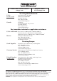
USB-4750 32-Channel Isolated Digital I/O USB Data Acquisition Module User Manual
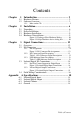
Contents Chapter 1 Introduction ..................................................... 2 1.1 1.2 Hardware Features............................................................. 2 Software Overview............................................................ 3 1.2.1 Chapter More on the CD ............................................................. 3 2 Installation ....................................................... 6 2.1 2.2 2.3 2.4 Unpacking .....................................................
USB-4750 User Manual vi
1 2 Introduction Sections include: • Hardware Features • Software Overview
Chapter 1 Introduction Thank you for buying the USB-4750 data acquisition mod- ule. The USB-4750 is a powerful data acquisition (DAS) module for the USB port. It features a unique circuit design and complete functions for data acquisition and control. 1.
1.2 Software Overview Omega offers a rich set of DLL drivers, third-party driver support and application software on the companion CD-ROM to help fully exploit the functions of your device. The Device Drivers feature a complete I/O function library to help boost your application performance and work seamlessly with development tools such as Visual C++, Visual Basic, 1.2.
USB-4750 User Manual 4
2 2 Installation Sections include: • Unpacking • Driver Installation • Hardware Installation • Hardware Uninstallation
Chapter 2 Installation 2.1 Unpacking After receiving your USB-4750 package, please inspect its contents first. The package should contain the following items: • USB-4750 Module • Shielded USB 2.0 Cable (1.8 m) • Companion CD-ROM (DLL driver included) The USB-4750 Module harbors certain electronic components vulnerable to electrostatic discharge (ESD). ESD could easily damage the integrated circuits and certain components if preventive measures are not carefully paid attention to.
2.2 Driver Installation We recommend you install the software driver before you install the USB-4750 module into your system, since this will guarantee a smooth installation process. The 32-bit DLL driver Setup program for the USB-4750 module is included on the companion CD-ROM that is shipped with your module package.
For further information on driver-related issues, an online version of the Device Drivers Manual is available by accessing the following path: Start/Programs/Omega USB-4700 Series/ Device Driver’s Manual USB-4750 User Manual 8
2.3 Hardware Installation Note: Make sure you have installed the software driver before you install the module (please refer to Section 2.2 Driver Installation) After the DLL driver installation is completed, you can now go on to install the USB-4750 module in any USB port that supports the USB 1.1/2.0 standard, on your computer. It is suggested that you refer to the computer’s user manual if you have any doubts. Please follow the steps below to install the module on your system.
Step2: Right click the “Unplug or Eject Hardware” icon on your task bar. Figure 2.1: Unplug or Eject Hardware Dialog Step3: Select “USB-4750 Device” and press “Stop” Button. Figure 2.2: Stop a Hardware device dialog box Step4: Unplug your USB device from the USB port. Note: Please make sure that you have closed the application before unplugging the USB device, otherwise unexpected system error or damage may occur.
3 2 Signal Connections Sections include: • Overview • Isolated Digital I/O Connections • Field Wiring Considerations
Chapter 3 Signal Connections 3.1 Overview Maintaining good signal connections is one of the most important factors in ensuring that your application system is sending and receiving data correctly. A good signal connection can avoid unnecessary and costly damage to your PC and other hardware devices. 3.2 I/O Connectors USB-4750 is equipped with plug-in screw-terminal connectors that facilitate connection to the module without terminal boards or cables. 3.2.1 Pin Assignments Figure 3.
3.2.2 I/O Connector Signal Description Table 3.1: I/O Connector Signal Descriptions Signal Reference Direction Description IDI<0~15> GND Input Isolated digital input channels INT<0,1> INT_G Input Interrupt trigger sources. INT<0,1>_ G - - Ground for interrupt pins. CNT<0,1> GND Input Isolated input counters IDO<0~15> GND Output Isolated digital output channels COM<0,1> - - Common pins for connecting inductive loads of isolated output channels GND - - Ground 3.2.
3.3 Isolated Digital I/O Connections 3.3.1 Dry/Wet Contact Support for Digital Input Each digital input channel accepts either dry contact or 0 ~ 5 VDC wet contact inputs. Dry contact capability allows the channel to respond to changes in external circuitry (e.g., the closing of a switch in the external circuitry) when no voltage is present in the external circuit.
3.3.2 Isolated Digital Output Connections Each of 8 isolated digital output channels comes equipped with a Darlington transistor. Every 8 output channels share common collectors and integral suppression diodes for inductive loads. Channels 0 ~ 7 use COM0, and channels 8 ~ 15 use COM1 as a common pin. If an external voltage (5 ~ 40 V) is applied to an isolated output channel (IDO 0 ~ IDO 15) while it is being used as an output channel, the current will flow from the external voltage source to the card.
3.4 Field Wiring Considerations • When you use USB-4750 to acquire data from outside, noises in the environment might significantly affect the accuracy of your measurements if due cautions are not taken. The following measures will be helpful to reduce possible interference running signal wires between signal sources and the USB-4750.
A 2 Specifications
Appendix A Specifications A.1 Isolated Digital Input Channels Interrupt Inputs Optical Isolation Opto-isolator ResponseTime 16 Input Voltage 5~50VDC, or dry contact A.2 DI0, DI8 2500 VDC 25 µs Isolated Digital Output 16 Channels 2500 VDC Optical Isolation Opto-isolatorResponse Time 25µs 5 ~ 40 VDC Output Voltage 100mA/ch. Max. 1.1A/total Max. Sink Current A.
WARRANTY/DISCLAIMER OMEGA ENGINEERING, INC. warrants this unit to be free of defects in materials and workmanship for a period of 13 months from date of purchase. OMEGA’s WARRANTY adds an additional one (1) month grace period to the normal one (1) year product warranty to cover handling and shipping time. This ensures that OMEGA’s customers receive maximum coverage on each product. If the unit malfunctions, it must be returned to the factory for evaluation.
Where Do I Find Everything I Need for Process Measurement and Control? OMEGA…Of Course! Shop online at omega.