OmiScan Gas Operating Instructions Part Number - I317719 US Issue 1 © Omitec 2008 Part Number - I317719 US - Issue 1 © Omitec 2008
Contents Introduction Introduction............................................................................................. 5 Power Management ............................................................................... 7 Safety Precautions ................................................................................. 7 Electrical Safety Precautions.................................................................. 7 Assembling the OmiScan Gas Analyzer...............................................
Contents Routine Maintenance & Cleaning Routine Maintenance............................................................................ NOx Cell Replacement ......................................................................... Calibration and Accuracy Checks......................................................... Cleaning ............................................................................................... 74 76 77 77 Technical Specification Technical Specification .........................
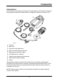
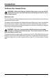
Introduction Introduction Introduction OmiScan Gas is an exhaust gas analyzer for spark ignition vehicles and comprises a fully portable handset with a base station and optional software to install on a PC. 2 5 7 8 1 4 9 6 3 OM1375 1. Handset 2. Base unit 3. Exhaust Probe attachment 4. Base unit exhaust pipe extension 5. Mains power converter supply 6. CD ROM with PC software 7. Vehicle power supply cable (optional) 8. USB cable handset to laptop 9.
Introduction There are two options available: 1. OM4720/5G • Measures 5 gases, provides live readings of all gases and λ • PC software to graph and/or diagnose emissions faults from gas readings 2. OM4720/4G • Measures 4 gases, provides live readings of all gases and λ • PC software to graph gas readings The OmiScan Gas system enables the measurement of four or five of the main exhaust gases emitted from a spark ignition engine.
Introduction Power Management The handset monitors both itself and the base station for the charge status of the battery packs. If either battery pack voltage falls below a predetermined level the handset will display a warning to cease testing and recharge the units. Approximately five minutes before the batteries reach the automatic shutdown point, a message is flagged to warn you of the low battery state and thus the imminent shutdown. 1.
Introduction Assembling the OmiScan Gas Analyzer Unpack the units carefully, checking off each item and component against the itemized packaging list included. If any component is missing or damaged, contact your supplier immediately. • The batteries in the base unit and the handset will need to be installed and charged before either unit can be used (see ‘Power Management’, page 7). • The base station battery compartment is on the underside of the unit, secured by two cross-headed bolts.
Introduction CAUTION: Before connecting the base station to the mains, ensure that you have read and fully understand the operating instructions given in this document. • Attach the exhaust sample probe to the water trap fitting (2) at the rear of the base station. • Attach the exhaust outlet pipe to the Exhaust Gas outlet (4).
Introduction OmiScan Gas Sample Probe WARNING: Before attaching any OmiScan Gas probe to the test vehicle, ensure that you have read and understand the safety precautions listed earlier in this manual. Exhaust probe The exhaust probe collects gas samples from the test vehicle exhaust, which are then analyzed by OmiScan Gas. The probe connects between the Sample Gas Input fitting (item 2 under ‘Assembling the OmiScan Gas Analyzer’, page 8) and the test vehicle exhaust pipe.
Getting Started Emissions Testing Getting Started Before attempting to test vehicle emissions levels, ensure that the base station and handset are fully charged (see ‘Power Management’, page 7) for remote operation. For on-road testing if the base station batteries are low, connect the base station to the vehicle supply cable (optional). With this configuration the batteries will not charge but the supply to the base station is maintained.
Getting Started • Settings - Results record, clock and general system settings • Language - Allows the user to configure handset in English, French or Spanish Gas Analyzer MAIN MENU Gas Analyzer PC/USB Mode Settings Lang, Idioma To access Emission Menu press the button with the pointing at Gas Analyzer. REMOVE THE PROBE Ensure the exhaust probe is in clean air -OK Follow the instructions and press the button. ANALYZER SETUP Please wait. . . . .
Getting Started Manual Power Down To power down both Handset and Base station at the same time, simply press and hold power button on handset for >1 second. Live Readings GAS ANALYZER Live Readings Simulated Tests System Checks Press the Readings’.
Getting Started • Gasohol E10 • Gasohol E20 Pressing Restart will display a screen asking for fuel type. LIVE READINGS Remaining Memory: 56Mins 40secs -OK X-Cancel The remaining memory will be shown. On pressing procedures will be displayed. -OK the series of screens and LIVE READINGS Ensure oil and coolant levels OK -Continue X-Abort A series of screen reminders are displayed: ‘Ensure oil and coolant levels OK’, press to continue, or press to abort’.
Getting Started ‘Ensure engine is running and up to temp., press to continue, or press to abort’. HC HANGUP Ensure the exhaust probe is in clean air -OK ‘HC HANGUP Ensure the exhaust probe is in clean air, press to continue. HC HANGUP HC residue check Please wait . . . . Limit: 20ppm HC: 00 9 secs X-Abort X HC HANGUP’ ‘HC residue check’, ‘Please wait’, Lim: 20ppm HC: XX’, ‘XXsecs’, press - to abort. On completion of the countdown the screen will briefly display ‘HC residue check passed.
Getting Started LIVE READINGS Display All. 2 Gas Display 1 Gas Display Exit Test X As soon as gas is sensed there is a request for the number of gases to display, all, two or one and also an ‘Exit Test’. If ‘1 Gas Display’ or ‘2 Gas Display’ is selected, an additional menu will be displayed listing the gases or outputs that can be displayed, which are CO, HC, O2, CO2, Lambda, NOx, Air Fuel Ratio (AFR) and corrected CO (COK). To make a selection, scroll up or down and press .
Getting Started TEST RESULTS 1 Live Readings Time: 09:11 Date: Feb 20 08 -Save X-Erase X When stop is pressed the screen displays ‘Test Result XX’ ‘Live Readings’ ‘Time: XX:XX’ ‘Date: XX/XX/XX’ press to save, or press to erase. SELECT MAKE Not recorded ACURA ALFA ROMERO ASTON MARTIN If saving, the next screen displays ‘SELECT MAKE’ and makes of vehicles can be scrolled using the and buttons. Press to select the make.
Getting Started LIVE READINGS Vehicle License No: ********** ----------OK X-Cancel - Move The next screen displays ‘LIVE READINGS’ ‘Vehicle License No:’ ‘XXXXXXXXXX’. The and buttons will set each character from A to Z and 0 to 9, when the first character is correct press the camera button. Move to the next character and repeat the procedure until the registration number has been added press . The bottom line, i.e. -OK -Cancel -Move will flash until is pressed again to confirm.
Getting Started REMOVE THE PROBE Please Wait. . . -OK X-Cancel Pressing the -OK will start a ‘System Purge’ procedure to remove any residual exhaust gases in the probe and pipework. SYSTEM PURGE Please wait . . . X-Cancel X On completion of the ‘System Purge’ the display will return to the Gas Analyzer menu. If pressing ‘Repeat’ the following sequence will occur: LIVE READINGS Remaining Memory: 61Mins 43secs -OK X-Cancel Pressing will display ‘Remaining memory: XXMins XXsecs’ -OK, -Cancel.
Getting Started LIVE READINGS Ensure oil and coolant levels OK -Continue X-Abort A series of screen reminders are displayed: ‘Ensure oil and coolant levels OK’, press to continue, or press to abort’. LIVE READINGS Ensure brake on and in neutral/park -Continue X-Abort ‘Ensure brake on and in neutral/park, press to continue, or press to abort’. LIVE READINGS Ensure engine is running and up to temp. -Continue X-Abort ‘Ensure engine is running and up to temp., press to continue, or press to abort’.
Getting Started HC HANGUP HC residue check Please wait . . . . Limit: 20ppm HC: 00 9 secs X-Abort X HC HANGUP’ ‘HC residue check’, ‘Please wait’, Limit: 20ppm HC: XX’, ‘XXsecs’, press - to abort. On completion the screen will briefly display ‘HC residue check passed.’ ZERO CALIBRATION Please wait . . . The base station will automatically carry out a ZERO CALIBRATION, on completion the progress bar will be replaced briefly by ‘Passed’. INSERT PROBE Exhaust probe check. Please wait . . . .
Getting Started If ‘1 Gas Display’ or ‘2 Gas Display’ is selected, an additional menu will be displayed listing the gases and outputs that can be displayed, which are CO, HC, O2, CO2, Lambda, NOx, Air Fuel Ratio (AFR) and corrected CO (COK). To make a selection, scroll up or down and press . In ‘2 Gas Display’ option, the selection will be tagged with an arrow. To deselect press again. Once the second gas has been selected, the handset will exit the menu and display the selected gases. LIVE READINGS λ: 0.
Getting Started LIVE READINGS Remaining Memory: 56Mins 40secs -OK X-Cancel Pressing -Save will store the results and the screen will change to live readings available memory. Pressing -OK will display the Gas Analyzer menu, after the ‘remove probe’ and system purge’ screens.
Getting Started CAT In this test all five gases HC, CO, CO2, NOx and O2 are analyzed to gauge the performance of a Catalytic convertor. The test will report that the Catalytic convertor is good, suspect or if the gas readings suggest there may be another fault which may not be related to the Catalytic convertor (only available for 5-gas option). CAT Please Wait. . . .
Getting Started CAT Preconditioning 5 secs X-Abort X A short preconditioning before continuing the fast idle test. CAT Fast Idle Test 30 secs X-Abort X If the gas level is within the limits the test will be complete and a report of ‘Within Limits’ will be displayed. CAT Outside Limits X = Quit = Extended test or X If the test fails an extended test can be started.
Getting Started CAT Run engine betweeen 2500-3000 RPM -OK X-Abort The vehicle engine speed must be set to within the range indicated. CAT Fast Idle Test 180 secs X-Abort X If the cat fails again a results page is displayed. NON-CAT FAULT CO = -0.00%, HC = 0ppm O2 = 20.97%, CO2 = 0.00% NOx = 0ppm -OK The test results can be saved or erased as required.
Getting Started TSI Test This test simulates the ‘first chance’ IDLE and HIGH SPEED modes outlined in the EPA91 Two Speed Idle emissions test. The test is designed to allow the user to evaluate how a vehicle may perform when tested officially. Note: This is not an official test. WARNING! This is NOT an official TSI test -OK, X-Cancel X or A warning screen displays the fact that this test routine is not an official test and can be used only as a guide to see if gas levels pass/fail the preset gas limits.
Getting Started TEST LIMITS TSI (Default) TSI (Custom 1) TSI (Custom 2) The test limits to be applied can be selected from the next menu screen. Simply scroll down and press to select. Note TSI (Custom 1) and TSI (Custom 2) limits can be edited to suit testing requirements using PC Gas Analyzer Software – see ‘Tests’, page 61‘ detailed in the PC Analyzer Software section of this manual. TEST LIMITS HC = 200ppm CO = 1.00% -OK, X-Cancel Test limits are displayed. Press to select other limits.
Getting Started TSI TEST ALLOW VEHICLE SPEED TO IDLE BETWEEN 350 - 1100 RPM -OK, Press X-ABORT to Start test. IDLE MODE HC CO (200) (1.00) = 54ppm = 0.05% 77 Secs X-ABORT The test readings will be displayed along with a test countdown. Maximum duration of test mode is 90 seconds. WITHIN LIMITS HC CO (200) (1.00) -OK, = 54ppm = 0.05% X-ABORT At the end of the IDLE Mode test the result will be displayed. Press the HIGH Speed Mode part of the test.
Getting Started HIGH SPEED MODE HC CO (200) (1.00) = 54ppm = 0.05% 77 Secs X-ABORT The test readings will be displayed along with a test countdown. Maximum duration of test mode is 90 seconds. WITHIN LIMITS HC CO (200) (1.00) -OK, = 54ppm = 0.05% X-ABORT At the end of the HIGH SPEED Mode test the result will be displayed. Press proceed. to TSI TEST RESULT WITHIN LIMITS -OK, X-ABORT The overall result of the TSI test will be displayed.
Getting Started TEST RESULT Default TSI TIME: 11:45 DATE: Oct 03 08 -OK, X-Erase Press to save or X to discard. If the test was carried out on a new vehicle the screen will prompt for make, year etc. before returning to the Simulated Test Menu. If the test was carried out on the last vehicle tested then the screen will revert straight back to the Simulated Test Menu.
Getting Started the test, so that the correct parameters can be set. At the end of the test, before saving the results you will be prompted for vehicle make, year etc. If the test is being carried out on the last vehicle tested then fuel type, vehicle make and year etc. will have already been saved by the handset and will be automatically added to the test result if it is chosen to be saved.
Getting Started PLEASE ENTER Amb. Temp. 68 F Rel. Humidity 45% -OK, X-Cancel ‘Camera’ - Redo The test requires values for both Ambient Temperature and Relative Humidity to be entered. These parameters are required for a Humidity correction factor which is applied to the NOx readings. Use the Up and Down keys to alter each reading then press enter. When both values have been entered the bottom line of the display will flash. Either press confirm or ‘Camera’ to change value.
Getting Started ASM TEST Set vehicle to Desired speed/load -OK, Press X-Abort to Start test. ASM TEST HC (150) = 75ppm C0 (1.00) = 0.30% NOx (1000) = 120ppm 77 Secs X: Abort The test readings will be displayed along with a test countdown. Maximum duration of test mode is 90 seconds. WITHIN LIMITS HC (150) = 75ppm C0 (1.00) = 0.30% NOx (1000) = 120ppm -Continue At the end of the test the handset will display the result either ‘Inside Limits’ or ‘Outside Limits’. Press to enter Save Result screen.
Getting Started WITHIN LIMITS Repeat Test? -OK, X-Finish REMOVE PROBE Ensure vehicle is Stationary and Parking brake on -OK If the option to finish test is taken the handset will display a prompt to remove the probe when the vehicle is stationary. The Analyzer will automatically detect the probe being removed before conducting a ‘System purge’ then returning to ‘Gas Analyzer’ Menu.
Getting Started Leak Test - Follow on screen instruction to check integrity of water trap and probe. Manual HC Hangup - Follow the on screen instructions to clear the system of residual HC gas. BENCH PEF VALUE 0.533 -OK Display PEF - Displays the current Petrol Equivalent Factor. Environmental Data - This function is for use by a calibration engineer and has no user functionality.
Getting Started PC/USB Mode PC/USB MODE Ensure USB cable is connected to the PC and the Handset X-Cancel X Simply follow on screen instructions.
Getting Started Manage Files MANAGE FILES Summary List by Date List by Plate Actions X There four items under Manage Files: • Summary • List by Date • List by Plate • Actions STORAGE SUMMARY 2 results Mem Left: 61m 43s -OK The ‘Summary’ screen displays the number of results stored and the amount of time left in memory, to exit from the screen press . -VIEW X- GOBACK 02/05/08 01/31/08 10:50 14:20 The ‘List by Date’ screen displays the list of stored tests by date in MM/DD/YY and time of the test.
Getting Started -VIEW X- GOBACK OU54XYZ*** -- The ‘List by Plate’ screen displays the list of stored by license plate (Registration N°). Each result is also listed by ‘Last Test First’. Where relevant a test result will be listed, e.g. CAT test may list ‘CAT OK’ or ‘Suspect CAT’. The integrity of the data saved will also be listed, e.g. if the test is cut short. To select a test use or keys, to view the test details press - VIEW or to return to ‘Manage Files’ menu press GOBACK.
Getting Started SET DATE AND TIME YY 200X MM Feb DD 27 -OK, DAY Wed hh 11 mm 07 X-Cancel The screen will display ‘SETUP DATE AND TIME’, ‘YY 200X’, ‘X’ will flash to indicate that it can be changed by using the and will increase or decrease the number. When the next number needs to be changed, e.g. if the year is 2009 and needs to be changed to 2010, the 9 will flash, when changed to 0, press the to move to the preceding number to change that to 1; this procedure is used for days, hours and minutes.
Getting Started View Thresholds CAT DEFAULT CO<0.3% HC<200 O2<1.00% CO2>14.0% NOx<100 -OK, X-Cancel When you select ‘View Thresholds’ the screen will display the threshold levels of the various gases for all of the simulated test procedures, TSI Default, Custom TSI 1, Custom TSI 2, ASM Default, Custom ASM 1, Custom ASM 2 and CAT. Press to toggle through thresholds one at a time.
Getting Started S/W Version S/W VERSION 00:01:31 -OK With selection of ‘S/W Version’ the screen will display the current down loaded handset software version; for example 00:01:31. This is not a user changeable item, press to exit. Factory Defaults FACTORY DEFAULTS WARNING: Lists downloaded from PC will be lost -OK, X_Cancel With selection of ‘Factory Defaults’ pressing will over write any lists that have been downloaded from the PC.
Getting Started LANG, IDIOMA US English Français Español To select language simply scroll down menu then press . The handset will automatically change language and then return to the Main Menu. Low Battery Indication Base station Low Battery - The battery icon on the handset flashes empty and the ‘POWER/LO BATT’ LED on the base station flashes. Handset Low Battery - The battery icon flashes empty and the ‘POWER/ LO BATT’ LED on the base station is not affected.
Getting Started Press to proceed and the handset will prompt you to save the results and to remove the probe from the exhaust. Note: Any saved data will state ‘Some Data Lost’ due to loss in Communications when the base station is powered down. Likewise, if the data is analyzed on the PC software, any data lost will be clearly indicated and all the gas readings for that part of the test will be recorded as zero. After data has been either saved or discarded, the handset will automatically shut down.
Getting Started TEST RESULT 3 Live Readings Time: 14:07 Date: Feb 21 08 -Save X-Erase If, when out of range, the handset stays out of range the message above will be displayed. LIVE READINGS Test terminated due to signal loss -OK You will be given the option of saving the data that was captured up to the point of lost communications.
PC Gas Analyzer Software System requirements PC Gas Analyzer Software The minimum PC system requirements to load the OmiScan Gas Analysis Utility software are: • Windows Server 2003, Windows Vista Business, Windows Vista Business 64-bit edition, Windows Vista Enterprise, Windows Vista Enterprise 64-bit edition, Windows Vista Home basic, Windows Vista Home Basic 64-bit edition, Windows Vista Home Premium, Windows Vista Home Premium 64-bit edition, Windows Vista Starter, Windows Vista Ultimate, Windows Vista
PC Gas Analyzer Software Analyzer Software Functions The OmiScan Gas Analyzer provides the facility to view the data collected by the OmiScan Gas handset, which is transferred to the PC. The data is analyzed in bar or line graph format.
PC Gas Analyzer Software Handset Results When the handset is connected to the PC with the USB cable, communication with the handset is established; the left hand pane displays all of the stored vehicle test results in the handset identified by test type, date, license plate details and manufacturer. The right hand side displays three icons representing the functions of ‘Save data’ , ‘Display data’ and ‘Delete data’ .
PC Gas Analyzer Software ‘Display Data’ will automatically load the data into the ‘Graph’ screen. The ‘Save’ button in the title bar is now activated and when pressed displays the same dialog box as in ‘Save Data’ above. ‘Delete Data’ displays a dialog box asking you to confirm deletion.
PC Gas Analyzer Software Search ‘Search’ allows stored data to be retrieved for later analysis, reference, historical recall etc. A general search for all stored data files can be started by pressing the ‘Search’ button (binoculars).
PC Gas Analyzer Software A specific search can be initiated from one or all of the following input cells: • Customer Name • Vehicle License • State • Make • Model • Type • Use Date Range with ‘From’ and ‘To’ date selection Any text item used as a search parameter can have a ‘wildcard’ character ‘*’ within it if the whole text is not known. For example, if searching for a vehicle but the whole registration is not known, entering ‘OU5*’ will match with any registration staring with those characters.
PC Gas Analyzer Software Results Detail The ‘Results Detail’ saves the test data under the vehicle rather than customer, therefore any new data from an already saved vehicle will be added to the vehicle records. The vehicle records are listed in the left pane in three areas. Car Symbol (License) • This lists details of make, type, year, fuel type, State and an area for you to add notes. (The data is down loaded from the handset but can be edited.
PC Gas Analyzer Software Man Symbol (Customer) • Cells are available to enter customer’s details. Clipboard Symbol (Test results) • Each test is identified by type, test name, date, tester’s name and notes area. Note: Selecting any test will enable the ‘Graph’ tab.
PC Gas Analyzer Software Graph Test Result can be presented in raw data line graph format or by test specific bar and line graphs. The available graph views depend upon the type of test carried out but the raw data line graph is always available. The test specific graphs (identified by ‘R’ on the graph icons) present a view of the data, but not the raw data, from only a portion of the entire gas recording. This may be, for example, the last 10 seconds of readings as an average.
PC Gas Analyzer Software The raw data line graph is available for all tests and is a plot of non-adjusted values against time. On the graph tab you can export the test results into a CSV file by pressing the file button on the top tool bar. You can also export the graph image as a bitmap by pressing the picture button on the top tool bar.
PC Gas Analyzer Software Bar graph: Readings that can be selected are: CO, CO2, O2, HC, NOx, MPH, AFR, and LAMBDA. On opening results the displayed readings will default to relevant gases. For example, if the test was a CAT then CO, CO2, HC, NOx and O2 will be displayed. Because all gases are recorded during a test they can be added to the graph by clicking on the gases in the DISPLAY bar down the left hand side of the screen.
PC Gas Analyzer Software Line graph: CO, CO2, O2, HC, NOx, MPH, RPM, AFR and LAMBDA are plotted against time. • Gases displayed depend on type of test, but like bar graph mode other gases can be added to plot. • Y axis scale can be selected to a chosen gas and its graph will become bolder. • Cut off limits will be shown on plot for the active series. • A Landscape graph (only available on the raw data graph view), showing a complete record of the gas readings, is under the main display.
PC Gas Analyzer Software 4. Add ‘Snap Shot/View Snap Shot’ Camera symbol – Click on camera symbol to add user comment and save. A green circle will be placed top and bottom of both graph displays to tag Snap shot. Note: Any Snap shot made during a test by pressing the Camera button on the handset will be automatically tagged on graph.
PC Gas Analyzer Software This will activate diagnostics for the current visible frame of graph. Any possible diagnosis made within this section will be displayed as a blue triangle as a prompt to move the cursor to that graph point. Once the mouse is over that point, the ‘INFO’ box will be displayed as normal. The purpose of this is to be able to quickly check a section of graph for possible diagnosable problems.
PC Gas Analyzer Software TSI Graph The left hand bar graph indicates CO and HC values for the idle mode section of the test. The right hand bar graph indicates the CO and HC values for the High Speed Mode of the test. A window in the top left hand of each graph will state ‘Inside Limits’ or ‘Outside Limits’ as the case may be. Note: ASM graph - Test result will be presented as a single bar graph indicating the CO, HC and NOx values from the test.
PC Gas Analyzer Software Tests Both the ASM and TSI simulated tests offered by the OmiScan Gas can be carried out using different limits (Cut points). Each Test offers two sets of Custom limits as well as a set of default limits. The PC analyzer software allows the custom limits to be changed on the handset. Click on Tests Tab then on the drop down menu arrow to list tests. Click on either ASM or TSI to list limits.
PC Gas Analyzer Software PC Analyzer software the limits will be displayed in green (In Sync). Click on either of the Custom limit boxes to display the individual gases and their limits. To change limits click on up or down arrows for the relevant gas to set the desired value. Click on limit box or press return on the PC keyboard to enter value. The test limit box will change to Red to show the test limits on the handset no longer match those set on the PC Analyzer software (Out of Sync).
PC Gas Analyzer Software Lists Vehicle make, vehicle types and testers can be edited and saved to the handset by using the drag and drop facility. Double click on any of the lists, ‘Vehicle Makes’, ‘Vehicle Types’ or ‘Testers’ and the current data stored on the handset is shown in the right pane. The + button can be used to add to a list, likewise, the - button can be used to delete from a list. Any list will be in alphabetical order.
PC Gas Analyzer Software If the Handset is not connected to the PC there will be no picture of the Handset and a warning ‘Handset Not Present’ will appear in the left pane and the status of any lists or tests will be red.
PC Gas Analyzer Software The lists for Vehicle type and Tester can be edited in the same way as Vehicle Make. Again like Tests to update the handset to the list held in the PC, click and hold over the specific list to transfer, and drag the list over the handset image and release the mouse button. On completion of downloading, the list box will change from red to green. Note: Drag and drop facility will be disabled whilst the handset is disconnected from the PC.
PC Gas Analyzer Software Shop: Contained in the PC and is added to the print out. If no printer is installed on the PC a print preview is not available and warning will be shown if the ‘Preview’ button is pressed.
PC Gas Analyzer Software Setup: Sets language and enables/disables tool tips. Help The help tab will link to a document providing a guide to the functionality tabs. The Navigation pane on the left also allows access to the diagnostic documents that are linked from the dialog box in the ‘Graph’ section if any of the gases are out of limits.
PC Gas Analyzer Software Communications The Bluetooth® Wireless Technology communications provides connection between the base station and the handset. The base station has a unique addresses and it is advisable to note this address in the data section of this manual, especially if either unit is replaced. Software Build Details of the software version and build can be accessed from the ‘Help’ function in the top bar left hand side.
Gas Analysis OmiScan Gas Analysis of Results Gas Analysis CO -Carbon Monoxide - Carbon Monoxide is the product of incorrectly burned fuel, so the obvious aim is to ensure that the CO level is as low as possible, the better the combustion the lower the CO. However, due to unavoidable inefficiencies with Internal Combustion Engine (ICE) there will always be an output of CO.
Gas Analysis • CO2 and O2 are indicators of the integrity of the exhaust system and/or the sample hose and probe • CO2is an indicator of combustion efficiency that peaks at or near the stoichiometric air/fuel ratio and decreases with rich or lean air/fuel ratios • If CO2 increases, O2 decreases (inversely related) If O2 increase, CO2 decreases (inversely related) During a cold start, and no secondary air injection, CO will be above 1% and the catalytic converter will be O2 starved and will not ‘fire’ and th
Gas Analysis Catalyst Systems Where AFR is used for Non-Cat systems, Lambda is used for Cat systems and the engine management systems control Lambda to 1. Any value >1 is a lean mixture and anything <1 is a rich mixture. Catalyst System Gases with Lambda Gas Perfect CO In Specification CO2 Highest possible Lambda 1 Minimum Maximum Problem 0.5 12.
Gas Analysis High Gas Levels Gas Possible cause High CO EVAP system problem PCV system problem Fuel system problem Control system problem High HC/CO Fuel system problem Running rich Blown head gasket High HC Mechanical system problem Electrical system problem Fuel system problem Running lean Warm air intake problem Cat problem EVAP system leak High NOx High combustion pressure High combustion temperature High O2 content High HC/NOx Cat problem 4 Gas Relationship CO CO2 HC O2 Problem H L H
Gas Analysis Lambda status Condition Result Too lean Poor engine power Misfiring at cruise speed Burnt valves Burnt pistons Scored cylinders Spark knock Slightly lean High gas mileage Low exhaust emissions Reduced engine power Slight tendency to knock Stoichiometric Best all round performance Slightly rich Maximum engine power Higher emissions Higher fuel consumption Lower tendency to knock Too rich Poor gas mileage Misfiring Increased air pollution Oil contamination Black exhaust 5 Gas - Catalyti
Routine Maintenance & Cleaning Routine Maintenance Routine Maintenance & Cleaning To ensure that the analyzer gives long and reliable service, regular cleaning and changing of the filters is necessary. Failure to change the disposable coalescing filter elements regularly may void warranty and service agreements. Check the cleanliness of the disposable coalescing filter (Part No. FL5720A or OM 4700/11/10 (Pack of 10)) at the start of each day.
Routine Maintenance & Cleaning DRAINING WATER FROM WATER TRAP To drain water from the water trap simply screw the brass drain fully clockwise. When the water has drained, screw the brass drain fully counter clockwise to seal water trap. NOTE: The drain only needs to be finger tight. Do not over tighten as this may deform the rubber seal. Always conduct a Leak Test after draining the water trap to ensure an air leak has not been introduced into the gas sampling chain which will cause false readings.
Routine Maintenance & Cleaning 4. Disconnect the cable from the red oxygen cell. It may be advantageous to gently prize the locking tab of the connector away from the mating half, to facilitate disconnection. 5. Unscrew the cell by hand (unscrew counter-clockwise). If discarding the cell, place to one side for later safe disposal. 6. With the new cell, ensure the “O” ring is properly seated against the thread abutment. Screw in the cell (clockwise) to hand-tightness but do not over-tighten.
Routine Maintenance & Cleaning Calibration and Accuracy Checks It is recommended that periodic Calibration and Accuracy testing should be carried out on the OmiScan Gas Analyzer to ensure reliable and accurate testing. It is also recommended that this be done once every 12 months on average. This can be carried out by an Omitec authorized Service agent Cleaning OmiScan Gas unit The surfaces of the analyzer cabinet can be cleaned with a soft sponge, dampened with a mild soap and water solution.
Technical Specification Technical Specification Technical Specification The OmiScan Gas unit (Part No. OM 4720/1) Environmental Operational temperature range 0°C (32°F) to 45°C (113°F) Operational temperature (nominal) 20°C (68°F) Storage temperature range -4°C (24.
Technical Specification Measurement range (OIML Class 0) Carbon monoxide (CO) range 0 to 15% vol. CO accuracy ±0.03% abs or ±5% rel. Carbon dioxide (CO2) range 0 to 20% vol. CO2 accuracy ±0.5% abs. or ±5% rel. Hydrocarbons as n-hexane (HC) range 0 to 2000 ppm vol. HC accuracy - 0 to 2000ppm ±10 ppm or ±5% rel. PEF Factor 0.490 to 0.540 Transducer measurement range Carbon monoxide (CO) range 0.00 – 15.00% CO accuracy: 0.00% to 10.00% 10.01% to 15.00% ±0.02% abs. or ±3% rel. ±5% rel.
Technical Specification Response time of analyzer: <15 secs to display 95% of final values (CO, CO2 & HC) Lambda Calculation (by Brettschneider formula) Lambda range 0.0 to 2.0 Resolution 0.01 Calculation of Lambda value according to Brettschneider (Source: Bosch Technische Berichte, VOL. 6 (1979) No. 4, p177-186) – As listed in OIMLR99 specification.
Technical Specification Ancillary Equipment Vehicle Supply Lead Cable length 6 foot For vehicles with auxiliary socket in the luggage compartment Pneumatic Specifications Flow Rate Analyzer Outlet (nominal) 1.0 l/min Sample Inlet 1.0 l/min Filtration Coalescing element-PVDF Fluorocarbon 95%+ efficiency at particles > 0.1 microns 57 mm length Oxygen Cell City Technology CiTicel AO2 Calibration Gas Minimum pressure 700 mBar above atmospheric pressure Flow rate 1.
Technical Specification Service and calibration frequency Calibration - At 12 monthly intervals Service Replace disposable filter element (0.1 µm) – Part No. OM 4700/11/10 (Pack of 10) Weekly – if in continuous use, else as necessary Single disposable coalescing filter (0.1 µm) – Part No. FL5720A Weekly – if in continuous use, else as necessary In Line hydrophobic pancake filter – Part No.
Technical Specification INDUSTRY CANADA: OmiScan Gas Handset OM4720/2: RSS210, RSSGEN Operation is subject to the following two conditions: (1) This device may not cause harmful interference, and (2) This device must accept any interference received, including interference that may cause undesired operation. Company Number and UPN Number: IC: 6220A-OM4720 ‘We hereby declare that product OmiScan Gas Handset OM4720/2 is a class 2 BT device (max 2.7 mW EIRP).
Technical Specification Spare Parts List Description Part number Top level kit OM4720 Base station OM 4720/1 OmiScan Gas Handset OM 4720/2 PC Analyzer Application Software CD OM 4720/3 Instruction Manual OM 4720/4 Exhaust Sample Probe complete with hose OM 4700/5 Battery Charger PSU OM 4700/6 Handset 2 battery pack OM 4700/7 Base Station 4 battery pack OM 4700/8 Sample Probe Hose extension OM 4700/10 Coalescing Filter (box of 10) OM 4700/11/10 NOx sensor OM 4700/12 Vehicle power le