OMNIA – 6FM Broadcast Audio Processor Installation and Operation Manual Version 1.00a January 2002 Omnia ● 2101 Superior Avenue Cleveland, Ohio 44114 USA TEL: +1 216.241.7225 ● FAX: +1 216.241.4103 ● Email info@omniaaudio.com www.omniaaudio.com Omnia Europe ● Johannistrabe 6 D-85354 Freising Germany TEL: +49 8161 42467 ● FAX +49 8161 42402 ● Email: europe@omniaaudio.com www.omniaaudio.
Manual Update Notification Due to the dynamic nature of audio processing products, this manual and all future manuals, will be considered as 'preliminary documentation'. Audio Processing is an art form that we take very seriously. As part of our dedication to this science, we will continue to update both the product and its documentation based on continued research, field experience and valued customer input.
Omnia-6 Manual version 1.00a Errata Sheet Applicable to Release software version 6.1.x. Page 31 – Schedule Please add: In order for presets to change during a schedule, the Preset checkbox in the New or Modify schedule dialog box must be selected. Leave it unselected when you will be using the trigger script function and click on the Scripts button instead to edit the trigger scripts. Page 78 - To set up a connection: Replace paragraph 2 with the following: 2.
January, 2002 Greetings! It’s with great pleasure to offer you our ultimate audio processor…Omnia-6fm! But first, I must share my gratitude with you as well. This second-generation FM processor has evolved from the original Omnia digital processors, and the worldwide acceptance of those has been quite humbling for me, to say the least.
TABLE OF CONTENTS Greetings Safety Instructions Hazard / Warning Labels Notices Specifications Warranty QuickStart Setup Guide ii iv v vi vii viii vix 1 – INSTALLATION Omnia 6-fm Pre-installation Tasks PC Card and Modem Installation AC Environment Considerations Installation and Connections Rack Mounting AC Connection Audio Inputs Audio Outputs Composite Outputs 19 KHz Sync Output SCA Input Ethernet Connection RS-232 Connection Interface Connection Powering Up 1 1 1 2 3 3 4 4 5 5 5 5 5 6 7 2 – THE OMNIA
Set Time Set Date About Change Password Lock Unit Load Defaults Load From Card Save To Card 34 34 34 34 34 35 35 35 Network Mac Address IP Address Gateway Subnet Mask Save Changes Reboot Display Test Broadcast 36 36 36 36 36 36 37 37 Security Config 37 3-THE OMNIA-6FM AND AUDIO PROCESSING Process Block Diagram Wideband AGC Phase Linear Crossovers Five Band AGC Enhancer Section Deep Bass EQ Phat Bass EQ Warmth EQ Stereo Expander Multiband Dynamic Peak Limiter Distortion Canceled Clipper Stereo Generato
Connecting via Modem 80 Custom modem initialization strings 81 Using an Ethernet based connection 83 Establishing a Remote Session 84 Terminal Programs/Direct Connection 85 Trigger Script Editor Dry Contact Closures Applying Control Voltages 86 86 86 Use of Trigger Scripts Paras and Sysparas 87 88 Using the Editor 88 Script Command Definitions Dayparts Presets Non-system Parameters System Parameters Setting New Syspara Values 90 90 90 91 92 93 Using the Script Editor Example: Switch to Mono Exam
SAFETY INSTRUCTIONS 1. Read All Instructions. All safety and operating instructions must be read before operating the product. 13. Overloading. Do not overload AC wall outlets, extension cords, or integral convenience outlets as this can result in a fire or electric shock hazard. 2. Retain All Instructions. All safety and operating instructions must be retained for future reference. 3. Heed All Warnings. All warnings on the product and those listed in the operating instructions must be adhered to.
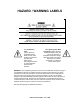
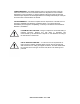
HAZARD / WARNING LABELS The Exclamation Point symbol, within an equilateral triangle, alerts the user to the presence of important operating and maintenance (servicing) instructions in product literature and instruction manuals. The Lightning Flash With Arrowhead symbol, within an equilateral triangle, alerts the user to the presence of uninsulated dangerous voltage within the product's enclosure that may be of sufficient magnitude to constitute a risk of electric shock.
CANADA WARNING – This digital apparatus does not exceed the Class A limits for radio noise emissions set out in the Radio Interference Regulations of the Canadian Department of Communications. Le present appareil numerique n'emet pas de bruits radioelectriques depassant les limits applicables aux brouillage radioelectrique edicte par le ministere des Communications de Canada.
NOTICES All versions of compatibility, trademarks, etc. of hardware and software products not made by Omnia, but mentioned in this manual or other accompanying material, are informational only. Omnia makes no endorsement of any particular product for any purpose, nor claims any responsibility for its operation or the accuracy of its presentation. Warranty registration and Software Updates Omnia 6's operation is almost entirely determined by software.
Omnia 6fm Specifications As of January 2002 – Version 6.01 Software Note: All measurements made with the supplied "FactTest2" preset, which is available in the Preset Submenu. Due to the nature of multi-band gain control and clipper algorithms used, the subjective sound quality of any audio processor bears little relationship to its measured electrical performance. Overall Specifications System Frequency Response Complies with the standard 50 or 75 microsecond pre-emphasis curve within ± 0.
A/D Conversion: Crystal Semiconductor CS5360, 24 bit 128x oversampled delta sigma converter. Linear-phase, 21.7 kHz anti-aliasing lowpass filter, with 0.0025dB maximum passband ripple. Analog Audio Output Configuration: Left/Right Discrete Stereo. Electronically balanced, floating and symmetrical. Flat or pre-emphasized response for either 50 or 75 microseconds. Source Impedance: 20 ohms. Load Impedance: 600 ohms or greater recommended, balanced or unbalanced.
External Sync Range: Accepts sample rates from 32kHz to 96 kHz. Used for synchronization of the Digital Output signal to an external reference. Automatically accepts sample rates between 32 and 96 kHz. Composite Outputs Composite Baseband Outputs Configuration: Two electrically independent outputs. Software based level adjustment. Source Impedance: 10 ohms or 75 ohms, internal jumper-selectable. Single-ended and floating over chassis ground. Load Impedance: 50 ohms or greater load is suggested.
Direct Serial: Standard RS-232, no hardware handshaking employed. Baud rates of 9,600, 19,200, and 57,600 supported. TCP/IP Ethernet: Emulates a Telnet session. Connectors: RS-232 port, EMI-suppressed DB-25 female connector. Industry standard EMI suppressed RJ-45 connector for Ethernet. Remote Control Trigger Interface Configuration: Eight (8) inputs, RS-232 level-compatible. Software sensing of both 'go-high' and 'go-low' transitions. Inputs are protected to +/- 15 VDC.
Warranty T his Warranty covers "the Products," which are defined as the various audio equipment, parts, software and accessories manufactured, sold and/or distributed by TLS Corp., d/b/a Omnia (hereinafter "Omnia"). With the exception of software-only items, the Products are warranted to be free from defects in material and workmanship for a period of two years from the date of receipt by the end-user.
Omnia 6 Quick-Start Setup Guide We know that you're probably in a hurry to get on the air with your new Omnia 6. If you have technical expertise and previous knowledge of audio processor fundamentals, using the following Seven-Point Quick-Start Checklist will get you up and running as quickly as possible. Please refer to the remainder of the Operating Guide for additional information. Refer to the following drawing for the location of the various connectors associated with the installation: 1.
1 Chapter 1 – Pre-installation We believe the Omnia-6fm is the easiest processor to install in its class, but please take a few minutes to read through this chapter before proceeding with the installation. Pre Installation Tasks This section offers common procedures for installing your new Omnia-6fm processor. Note that there are additional installation and operation tips presented in Chapter 4 that may pertain to your specific installation.
2 The Omnia-6fm also contains a second PC Memory Card that contains the software for the Front Panel. This card has been pre-installed at the factory and is located under the top cover on the right-hand side of the Front Panel circuit board. Please make sure the AC power is off and disconnected from the unit before removing the top cover and removing or replacing the card. Important Note 1: The PC Cards used in the Omnia-6fm are not generic PCMCIA cards that can be bought in any local computer store.
3 Installation & Connections Throughout this section reference is made to “software parameters.” These are part of the Graphical User Interface, which is covered in detail in Chapter 2. Rack Mounting The Omnia-6fm requires 3RU (5.25" [37 mm]) of rack space. Rack mount the unit using four rack screws. If only two screws are going to be used, they should be in the bottom holes in the Omnia front panel.
4 When power is first applied, it takes approximately ten seconds to load the DSP code from the rear-panel PCMCIA memory card. During system power-up, the front panel LCD screens display several status screens while the operating software and DSP code is loaded. Once the main Omnia-6fm Main Menu is shown on the right screen, and the Meter Screen is shown on the left display, the unit is ready for use.
5 Composite Outputs (BNC) These two low impedance outputs (Composite 1 and Composite 2) are each capable of driving up to 100 feet of RG58A/U coax cable. The output levels are individually adjustable between the outputs so the unit can operate as a “composite DA” to drive a variety of equipment. The output levels and other stereo generator settings are set through software parameters in the Encode menu. An internal jumper sets the output impedance to either 10 ohms (the factory setting) or 75 ohms.
6 case, you must use a standard, straight-through serial cable (not a null modem cable) between the RS-232 connector and the serial port connector on the computer. Typically, a DB25 male to DB-9 or DB-25 female cable will be used, with the DB-25 male end of the cable attached to the Omnia6-fm. The setup and operation of the Omnia Remote Control application is covered in detail in Chapter 6.
7 Powering Up When the Omnia-6fm is first turned on, an operating system start up screen is displayed on the left-hand display. Under normal conditions, it should appear as: If the Network Configuration has been changed from the factory defaults, a second screen will appear when the unit does a warm boot to load the network parameters: After approximately ten seconds, audio will be present from the analog, composite and headphone outputs.
8 This page intentionally left blank to maintain pagination 8 Omnia 6 Use and Installation Guide – Version 1.
9 Chapter 2 The Omnia 6 User Interface Now that your Omnia-6fm is rack-mounted, connected to a program audio source, and turned on, you’re ready to learn how to operate it! This chapter covers the Graphical User Interface, your window into the Omnia-6fm processor. A front panel jog-wheel with integral push switch and twin Active-Matrix Color LCDs make up the Omnia-6fm Graphical User Interface.
10 Using the Jog Wheel The main user control for the Omnia 6 is the large, easy to use jog wheel with its integral push-switch. Using the control is both intuitive, and efficient, making it easy to navigate the menu structure of the Omnia 6. Processing changes and system adjustments can be quickly made with ease without having to remember multiple controls, their positions, and what they do in each menu. The behavior of the Omnia 6's menu system is consistent across pages and is easy to learn.
11 Level Meters & Processing Bargraphs The horizontal meters show digital sampleaccurate peak and VU representations of the left and right input and output levels, while the vertical bargraphs show processing activity of the various algorithms. The currently selected Preset Name is displayed in the bottom left corner of the Meter Display, while the current time is displayed in the lower right corner.
12 Main Menu Display The Omnia-6fm Main Menu is displayed on the right hand LCD screen, and offers seven menu selections: Preset, Schedule, Process, Encode, Input, Output, System. Below the Main Menu in the lower left corner of the display is a multipurpose "Help Text" box. The Omnia-6fm menu system has been designed to be intuitive and simple to use, with a minimum of layered submenus. Most operating parameters are found on one of the seven main menus.
13 In all submenus with adjustable parameters, rotating the jog-wheel sequentially highlights each control or selection choice, along with the Home icon and the Headphone level button. In the Process submenu, the parameter adjustment windows have an “X” Close Window icon in the upper right corner (as shown in the AGC Mixer window below). Highlighting this icon and clicking closes the window, returning the user to the Process submenu, one level above.
14 Remote Control Session via Network Indicator An exclamation mark inside a yellow triangle will show up in the lower left corner of the Main Menu screen when a Network remote session is in progress. A remotely connected network session has priority over local control of the front panel, so during a Network remote session the Main Menu will be grayed out. Omnia 6 Main Menu The triangle with exclamation mark signifies that a TCP/IP Remote Control session is active.
15 User Interface Tutorial – Input Source Selection and Peak Level Setting The following two exercises are a useful introduction to the user interface. Start from the Main Menu (as displayed when the unit is first turned on). The first exercise changes a parameter selection (the Input Source selection): 1. Rotate the jog-wheel to highlight Input. 2. Click the jog-wheel (push on the wheel once) to bring up the Input window (shown below).
16 The next exercise adjusts a parameter that uses a value (the L / R Input Gain setting): 1. Highlight Input and click to open the Input window. Input Menu Showing Input Gain Controls 2. Rotate the jog-wheel to highlight Input Gain Left, and then click the jog-wheel to select the control. 3. Rotate the jog-wheel CW to increase the input gain. Rotate the jog-wheel CCW to decrease the input gain. The gain in dB is shown below the “control.
17 The Menu Tree The menu tree for the Omnia-6fm is shown in the following two pages. The seven main menu items are bold for clarity, with their branching parameter choices shown in the order in which they are encountered in the menu system. The first four menu options and their branches are shown below: Omnia 6 Use and Installation Guide – Version 1.
18 The next three Menu Options are shown below along with their associated branches: 18 Omnia 6 Use and Installation Guide – Version 1.
19 Menu Items This section presents an overview of the seven submenus (Preset, Process, Input, Output, Encode, Schedule and System) and their parameters. The Menu Selections section, starting on page 2-6, gives indepth descriptions and usage instructions for each submenu item and parameter selection. Preset Omnia-6fm is equipped with numerous factory presets that can be used to instantly configure the processing for common applications.
20 Since you cannot build a preset from scratch, a factory preset must be used as a starting point for creating your “signature sound.” Each signal processor section (from the Wideband AGC to the Clippers) can be individually selected, and its parameters adjusted as required. Once the processing is adjusted, the Preset menu "Save As" function is used to save your newly edited factory preset to the PC Card as a new user preset.
21 Encode This submenu contains the adjustments for the DSP based Stereo Generator. The Output Levels for Composite Outputs 1 and 2, the Stereo Pilot Injection Level and Phase, and the SCA Injection Level and Stereo Separation parameters are adjustable here. Like the Input and Output menu choices, these menu items are typically adjusted during installation, and are saved as a System Configuration (see above).
22 System Numerous maintenance and utility functions are found in this submenu. System data is saved here, and various Security options are available to prevent tampering by unauthorized personnel. There are also controls for setting the serial RS-232 communications baud rate, TCP/IP networking parameters, the date, time, and the Screen Saver backlight off timeout interval.
23 Preset This submenu is active under Level-3 password access, or at Security Levels 1 or 2, as defined in the Security Config screen. In addition to the Preset name list, there are five functions available in this submenu: Choose, Modify, Save Preset, Save Preset As and Compare. Preset Submenu Preset List Lists all of the presets, factory and user, that are on the PC Card inserted into the memory card slot on the rear panel of the Omnia-6fm.
24 Save Current As Opens up a window so a new preset name can be entered. Preset names can be up to 12 characters in length. Rotating the jog wheel clockwise scrolls through the capital letters of the English alphabet first. Rotating it counter-clockwise scrolls through the numeric characters first, and then through the lower case English alphabet. Click the jog-wheel to select a highlighted character to change. Then rotate the jog-wheel to step through all the possible characters.
25 Input This submenu has seven items: • Input Gain Left/Right, Master Drive • Input Source Selection • Invert Both Channels Option • Input Mode Selection • HP Filter Selection • Phase Rotation Selection • Pre-Emphasis Selection Input Submenu Input Gain Left / Right These controls set both the analog and digital input peak levels. For an analog signal, the control range is from -18 to +12. For digital signals, the range is from -30 dBFS (deciBels below digital Full Scale) to 0 dBFS.
26 Input Source Selects between the discrete Left/Right Analog input or the AES/EBU Digital input. Input Mode Selects how input audio is routed and processed by the Omnia-6fm. Highlight and click on the parameter selection to set the mode. The selected Mode is shown with a dot in the box next to the name. The factory default selection is Stereo. The other available modes are: Stereo: the left and right input channels are processed separately.
27 Pre-Emphasis For the transmission side of FM broadcasting, some form of high-frequency boost, or pre-emphasis is used. The most commonly used values of pre-emphasis are 50 and 75 µs (microseconds). For North and South America, 75 µs is used. In Europe, Australia and New Zealand, 50 µs is employed. The factory default preemphasis setting is 75 µs. The pre-emphasis selection affects the operation of the audio processing and is applied to the composite, discrete, and digital outputs.
28 De-Emphasis The Left/Right outputs are pre-emphasized under normal circumstances, such as when feeding an outboard stereo generator or discrete microwave studio-transmitter link. The same applies when feeding a digital exciter from the AES/EBU output. These outputs can also be de-emphasized for installations that require a flat frequency response, as is the case when feeding other types of studio to transmitter links. The factory default de-emphasis setting is 75 µs.
29 Multiplex Power Limiting In certain parts of the world, the power of the overall multiplex signal must be controlled to prevent or reduce adjacent channel interference to closely spaced stations. The currently enforced standard falls under the ITU BS-412 regulations. The Omna6-fm has a very effective Multiplex Power Limiter algorithm that may be enabled to comply with these regulations.
30 Encode Six parameters are set under this submenu: • Composite Output 1 • Composite Output 2 • SCA Level • Pilot Injection • Pilot Phase • Stereo Separation Encode Submenu Composite Output 1 & 2 These controls individually set the level at the two separately buffered rear-panel composite outputs. The output level adjustment range is between 1.25 and 9.5 volts peak-peak. Use the jog-wheel to select the modulation level for each composite output.
31 Pilot Phase This parameter sets the phase relationship between the 19 kHz pilot and the 38 kHz suppressed carrier. The system default is 0.0º. The performance of the DSP based digital stereo generator is theoretically perfect, however should the phase need adjustment in order to offset time domain errors in the overall transmission system, the pilot phase can be adjusted ±32º, in 2º increments. We recommend that a calibrated modulation monitor be used for this adjustment.
32 New Used to create a new Schedule. Highlight and click on New to open the Modify Schedule window and create a new Daypart Schedule. Modify and Remove Used to modify or remove an existing schedule. Highlight and click on the Schedule List, then highlight and click on the Daypart Schedule you wish to modify. Highlight and click on Modify or Remove. Modify will open up the Modify Schedule window and allow you to modify the settings of the selected daypart.
33 System This submenu allows you to perform housekeeping on the Omnia-6 operating system. Many items on this menu are available only to those having Level 3 security access. There are thirteen parameters or selections: About, Change Password, Lock Unit, Load Defaults, Load from Card, Save to Card, Network, Security Config, Current Time, Current Date, Port Baud, Security Level and Backlight.
34 Backlight This setting determines the time it takes for the LCD screens to turn off after the last time the jog wheel has been used. The selections are 1 min, 5 min, 15 min or 1 hour. To preserve the life of the LCD backlight, there is no option available for continuous operation. Set Time Sets the current time for the unit, which must be set before dayparts can be used. The time is set using the familiar “turn and push” action of the jog-wheel.
35 Lock Unit Highlight and click to immediately lock the unit. A dialog box is presented for password entry to unlock the unit. Note: You can only unlock the Omnia-6fm at the same or higher access level than it was at when it was locked. In other words, if the unit was locked while at Level 3, then only the Level 3 password will unlock the unit. If the unit was at Level 2 when it was locked, then either the Level 2 or the Level 3 passwords will unlock it.
36 Network Opens up a window to set the Ethernet communications protocols (IP address, default Gateway and Subnet Mask info). Make sure to Save Changes before exiting this window. There are also options to allow you to Save Changes to the network settings, Reboot Display (front panel only), and send a Test Broadcast packet out to the connected network. Network Submenu MAC Address The factory assigned, twelve-digit, hexadecimal hardware address of the Omnia 6 Ethernet interface.
37 Reboot Display After network changes have been saved in the above step, the front panel must be rebooted in order to make the changes active in the network hardware. Test Broadcast The Test Broadcast button sends a series of UDP packets out over the network interface. The message contained in the packets is "An Omnia Broadcast Datagram". These test packets may be used to troubleshoot routing and other issues on the customer's network.
38 This page intentionally left blank to maintain pagination 38 Omnia 6 Use and Installation Guide – Version 1.
39 Chapter 3 The Omnia-6fm and Audio Processing This section presents an overview of the Omnia-6fm processor. Refer to the block diagram shown on the Process submenu to provide a functional order to the various processing sections. Note: More detailed technical information about the audio processing employed in Omnia-6 can be found in the Technical Papers section on the Omnia web site (www.omniaaudio.com). Your Omnia-6fm comprises nine general processing sections as shown below.
40 9. Multiple clipper stages (Clip) at the output. Wideband AGC: A very flexible wideband leveler section provides smooth, transparent control of the input program. This is achieved through two significant Omnia innovations, a dual referenced release gate and a hidden, intelligent “makeup” gain algorithm.
41 AGC and Limiter sections. Deep Bass EQ: For those who demand thunderous bass. Up to 12 dB of “thunder” can be added to shake your listeners’ walls! This is not merely a simple bass EQ, but a sophisticated concept which considers the time alignment of low frequencies as they pass through the entire system. This allows loud, clean, thunderous low end, with no sacrifice to the overall loudness of your signal.
42 approached. Stereo separation is typically greater than 65 dB. Suppression of the 38 kHz carrier is greater than 75 dB. User parameters include Separation, Pilot Phase, Pilot Level and Composite Output Level. Selectable Composite Clipper with Phase Linear Composite Low Pass Filter: This feature is useful for those who wish to “turbo-charge” their FM signal. This clipper is specially designed to not interfere with the 19 kHz stereo pilot.
43 Chapter 4 This chapter presents installation and operation information specific to the Omnia-6fm. A Parameters Worksheet, located at the rear of this manual, may be photocopied to record the parameter settings used for specific processing presets. Processor Location Believe or not, this is an important consideration! Where you choose to locate the processor—at the studio or at the transmitter—can have a profound impact on the overall performance and your stations' loudness on the dial.
44 could be due to either AC coupling in the STL system or “bounce” generated by either the modulator or demodulator of the STL. Sometimes it’s a little of both! If you notice any “grass” exceeding the peak level of the low frequency waveforms, there could be noise getting into the system. This can occur if the RF path is noisy due to RF signal loss.
45 a good first step — good source material! Studio Microphone Processing This may appear trivial, but the perceived sound of “live” voices over the air can change dramatically with different microphone processing systems. There is a high probability that the sound of your on-air microphones will change when you change on-air processors. If you utilize microphone processing, you may have to readjust it to suit the operation of your new processing system.
46 Omnia-6fm Connections Output Connection Options Tests have shown that post-processing audio power in the low frequency region is so strong that it may affect the performance of some exciters. It is imperative that your exciter have a dual speed PLL in the AFC, otherwise it may unlock. If one of your processing goals includes solid, powerful bass on air, this is an important key point that cannot be overlooked or loudness will be lost due to inefficient modulation.
47 Finally, The New Frontier” on the Omnia Tech Info web page at www.omniaaudio.com . When using the AES/EBU outputs to drive a digital STL or exciter, your Omnia-6fm’s sampling rates must be set to match the lowest internal operating sampling rate used in any device which follows the Omnia-6 in the audio chain. You will find these options in the Output Menu; available selections are 32kHz, 44.1kHz, 48kHz, and 96kHz. Failure to select the proper output sampling rate will result in generation of overshoots.
48 This page intentionally left blank to maintain pagination 48 Omnia 6 Use and Installation Guide – Version 1.
49 Chapter 5 Fine Tuning Your Sound Many broadcasters will be amazed at the dramatic sonic improvements Omnia-6fm delivers right out of the box and using one of the included factory presets. Some will want to tailor one or more of the presets slightly to create a more “custom” sound for their station. Still others will wish to really delve in and significantly modify the parameter settings to create their own unique “signature sound.
50 realize that in our business today, time is a precious commodity. But please don’t try to install the Omnia6fm in between other major projects or during the week your boss or your assistant is on vacation. Make certain in advance that the staff members who helped you set your objectives will be available to consult with you when you adjust the processing parameters. How much is enough time? We feel that working with a system for at least a week is a good starting point.
51 The Meter Display In addition to the Input and Output Levels display, the Meter Display also provides processing information in the form of vertical bargraphs, which indicate both AGC and Limiter Processing activity. AGC Metering Limiter Metering Omnia 6 Main Metering Screen AGC Metering The bargraphs for the AGC sections can indicate up to 25 dB of gain reduction. When the “bouncing ball” indicators on each bargraph change to RED, the Gate function is active for that band.
52 Interpreting the Gain Reduction Meter Displays Through careful observation of the processing bargraphs, significant information can be acquired and analyzed about the audio signal on a moment-by-moment basis. The yellow bar shows the average value of the gain reduction, while the floating ball indicates the peak value of gain reduction.
53 program's RMS energy. During gain calculations, the incoming program's “average” level is established, and gain adjustments, if needed, are made based on those calculations. This is why the AGC sections will appear to move slower than the limiters ... they are making changes, as needed, over relatively long time periods. The intent of the Limiter sections is to control the peak levels. This is accomplished by finding and controlling the highest peak of the audio waveform.
54 Always remember that when “crafting” that special sonic personality for your station, Omnia-6fm gives you the power to create a sound that can be totally different from, and far better than that of your competitors. We've enjoyed giving you that power, and we hope that you enjoy using it! A special preset, “PROOF OF PERF” can be loaded in order to stop all audio processing in the Omnia-6fm, while still passing signal through all of the processing sections.
55 move the highlighting to the selection in the preset name list. Rotate the jog-wheel clockwise to scroll down the list, highlighting each preset as it goes. Once you have highlighted the desired preset name, just click once to load that preset into the Omnia-6fm. To exit the preset selection list, rotate the jog wheel counter-clockwise until the option is highlighted. Then click once.
56 blocks are highlighted. Clicking the jog-wheel opens up the parameter window for that processing block. Parameter adjustment is accomplished using the previously described method—clicking the parameter to select it, turning the jog wheel to adjust it, and then clicking to save the selection and change the jog-wheel back to Highlight Mode. The following sections provide insight into each of the processing blocks and their associated adjustments.
57 Attack and Release time constants. As the attack/release times are modified, the system also scales the Make-Up Gain time constants. Use less makeup gain for processing more faithful to the source material; use more makeup gain for greater loudness and “density.” The Gate Threshold control sets the level at which gating of the AGC occurs, which “freezes” the gain during short pauses.
58 AGC Crossover (XO) The audio signal from the WB AGC section is divided into five user-adjustable frequency bands within the AGC XO section. The crossover frequency points for the five bands are controlled by the four controls along the bottom of the window. The various crossover choices are: Low Freq. to Mid Low (LF/ML) – 100Hz, 120Hz, 150Hz, 190Hz, 250Hz; Mid Low to Mid High (ML/MH) – 400Hz, 500Hz, 700Hz, 1Khz, 1.5Khz; Mid High to High Freq. (MH/HF) – 2.5Khz, 2.8Khz, 3.2Khz, 3.7Khz, 4.
59 Multiband AGC Windows Each of the multiband AGC's has its own set of controls similar to those in the Wideband AGC section. The four controls in these windows, Attack, Release, Make-Up Gain and Gate Threshold, and the two parameter selections, RTP Speed and RTP Level, function like those in the Wideband AGC window. Adjustment strategies are similar, however in the mutiband AGC sections adjustments are on a "perfrequency band" basis.
60 value is –10dB. Keep in mind that the RTP function must be activated for this parameter to be relevant. Note also that for some presets, small changes we made to the compression ratios will affect the displayed value of the RTP. For instance, if you set the RTP gain value to "10" but notice that the band gain recovers to –12 when gated, it is because we have set a slightly higher ratio for that band.
61 Enhance Each of the Deep Bass, Phat Bass and Warmth controls can boost the level up to 12 dB. Be careful here not to overdrive the following limiter sections or over emphasize these lower frequency ranges. When used properly this specialized low frequency enhancement tools can deliver the thunderous bass and warmth that the Omnia is known for, and it can do so without making the sound muddy.
62 point. The overall stereo soundfield will appear wider and be much more consistent sounding between program sources. The smart Stereo EXP algorithm turns off when a mono program source is present. If you find that your mono programming sounds a bit thin, you can add a small amount (2 dB) of Phat Bass boost to restore warmth to the overall air sound.
63 Multiband Limiter Windows Limiter Submenu – SL Limiter shown as example The controls in these adjustment windows are similar in function to the previously described AGC stages. However, there are only four controls for the limiters. The Attack and Release controls work similarly to the AGC sections, but are of course much faster on overall action. There are also two new parameters as well. The first is the Hold Threshold.
64 Final Mixer (Mix) Limiter Mixer (final mixer) This is the final summing point for each of the multiband limiter sections before the signal reaches the final clipper. Care should be used when adjusting this section, as too much level from any particular band could cause an excessive amount of clipping distortion to that range of frequencies. A tribute to this fact is the extremely fine, 0.
65 Clippers (Clip) Clipper Submenu Bass Clip Threshold: Limiter bands 1 & 2 have their own clipper and time-aligned low-pass filter in order to reduce IM distortion in the main clipper. The Bass Clip Threshold control sets the threshold of the bass clipper referred to the clip level of the main clipper. A higher threshold (counter-clockwise) will reduce the amount of bass clipped by the bass clipper but cause a corresponding increase in the amount of bass clipped by the main clipper.
66 from affecting the stereo pilot and SCA regions. Adjusting and Using the BS-412 Multiplex Power Limiter The Output Menu contains controls for the Omnia 6's proprietary ITU BS-412 Multiplex Power Limiter algorithm. This algorithm is an enhancement of a DSP based design first pioneered by Frank Foti as an enhancement for the original Omnia FM product. ITU BS-412 Multiplex Power Limiter Controls The concept behind the Multiplex Power Limiter is deceptively simple.
67 The graph below was captured from an Audemat DFMA2 measuring instrument. It shows the analysis of a 30-minute segment of audio as processed by the Omnia 6 with the ITU BS-412 Multiplex Power limiter enabled and adjusted to the 0.0dB setting. Note that at no time during the measurement interval does the average power exceed the zero dB reference line.
68 Saving, Renaming and Deleting Presets Saving Presets Upon completing a preset editing session, the processing changes should be stored. This way they can be recalled later, or even transferred to another Omnia6-fm. Storing the settings writes them to the PC memory Card, either by overwriting an existing preset, or by creating a new preset. It is also possible to delete presets that are no longer needed, and deleting unused presets frees up memory space and makes it available for saving newer ones.
69 After entering the preset name’s last character, rotate the jog-wheel until the √ Checkmark is highlighted. Click the jog-wheel to save the new preset. If you wish to cancel the operation, highlight the X instead and click the jog-wheel. The operation is canceled and the Preset list and menu is again displayed. Note: You cannot save a preset using any of the factory-supplied preset names. A different preset name must be used, using the Save As menu option.
70 processor. Omnia-6 makes loudness an effortless exercise for all formats. One more confession. It’s also OK for your station to not sound loud, yet sound incredibly musical and grunge-free, because the Omnia-6 has given you the choice. Omnia6-fm is a system that maximizes the audio quality of your signal, yet at the same time satisfies your competitive requirements.
71 • Increase the Drive to each section using the controls in the Limiter XO screen. • Increase the Release time settings in each band so that they operate faster. • Set the Hold threshold to a lower value. 3. Drive the Clipper sections harder. 4. A combination of the above steps, but in small increments! It might sound crazy, but it’s true! In this situation, resist the temptation to make too many changes at once.
72 • Reduce the Release time to operate slower. • Reduce the amount of Make-Up Gain. Backing off the clipping sections first will allow the processing to retain a level of competitive loudness while enhancing quality, and the overall dynamic texture will be affected less. Start with reducing the Clipper amount in 0.5 dB steps. It’s surprising how much detail can be restored from just a small change of 0.5 dB.
73 might be noticed on midrange/presence frequencies whenever a sustained bass note is present. An example of this would be a strong bass signal “underneath” a sustained vocal passage. The vocal passage will begin to sound as if it “warbles” a little bit. This is a sign that the over-processed bass energy is pushing the vocal frequencies in and out of the clipper unnecessarily.
74 This page intentionally left blank to maintain pagination 74 Omnia 6 Use and Installation Guide – Version 1.
75 Chapter 6 Remote Control Software The Omnia Remote Control software is a Windows (Windows 95, NT 4.0, or higher) software program that allows remote access to the Omnia-6fm processor adjustment using any PC running the aformentioned versions of Microsoft Windows©. Note that remote software for the Omnia6-fm is unique to that product, and versions of Omnia Remote Control for our other audio processors will not work with Omnia6-fm.
76 Omnia6_remote1.exe onto the computer's hard disk and places the program name Omnia Remote Control in the Start Menu. The default location for the copied files is "C:\program files\Telos_omnia\omnia6". When the program is freshly installed but has not yet been run, "Omnia6_remote1.exe" is the only file in the specified folder. However, the first time that the program is run, it will create a small new file called "connect.dat", which contains your connection type information.
77 Checking the Version Number of your Omnia 6 Remote Control Program You can check the version of your Omnia Remote control program by clicking on the "About" option under the "Help" menu option. The Omnia 6 remote Control Version number is shown here. The Omnia 6 Remote Control "About" Screen While you are configuring the data for the various connection types, the Omnia Remote Control software can be run without having to connect it to the Omnia-6fm. Start the Omnia6_remote1.exe program.
78 Under the Options Menu, select "Edit Connection". A new window will open, and a default “New Connection” option will be displayed. Enter required information into each of the configuration boxes. Edit Connection Menu in Omnia 6 Remote Control In the left side of the "Edit Connection" window will be the list of any connections that are currently contained in the 'connect.dat' configuration file.
79 you do this, the parameters required for direct serial or dial-in via modem will be grayed out. Then, only the TCP/IP address of the Omnia that you wish to connect to must be entered. Note: If you are connecting via Direct Serial or Modem, you should not check the "Connect over Ethernet" box! 4. If connecting via Direct Serial or Modem, then select the COM port that you wish to use on your PC.
80 Remote Control Using a Direct Serial Connection In the Edit Connection window, create a New Connection and name it. Then fill in the Password box (the default password is 'tomtom'-lower case only!). The password may be changed at any time using the File Menu "Change Password" option. Note that you must be connected to the Omnia in order to change the password, and that the password change becomes valid the next time you attempt to log in with Omnia Remote control.
81 Using a Custom Modem Initialization String A custom Modem Initialization String is sometimes required in order to control the behavior of the modem in special circumstances. While there are many different initialization string possibilities, the most common one modifies how the modem handles dial tone. Sometimes the modem may be connected to a circuit that does not provide the US standard 350/440 Hz dial tone, and in this case, you need to tell the modem to ignore it.
82 Given this information, a possible initialization string example configured to ignore the dial tone before dialing, could be: ATX0w,xyyyzzzz or ATX0w-,x-yyy-zzz Where "AT" is the start of the standard modem command string, and; Where "X0" tells the modem to ignore busy and dial tone detection, and. Where "x" is the number to dial to reach an outside line (if required), and; Where "," is a pause, and; Where "yyy" is the dialing prefix, and; Where "zzzz" is the dialing suffix.
83 Using a Direct RS-232 Connection for Local Communications When a computer can be located near the Omnia-6fm, it may be convenient to use a direct serial cable connection rather than dial up. Use a standard, straight-through serial cable - null-modem cables will not work! A typical serial cable will need a DB-25 male connector for the Omnia-6fm end, and probably a DB9 female connector on the computer end. You should verify the exact type required by your computer.
84 Establishing a Remote Connection To establish a connection with the remotely located Omnia-6fm, return to the Options Menu and select Connect, which brings up a list of connections you have defined. Double-click on the name of the desired connection, or highlight it to select it and press OK. The connection will be established after a short pause, and you should see the bargraph meters become active when a connection has been established. Omnia 6 Remote Control after connection is made.
85 Using a Terminal Program and Direct Connection It is sometimes useful to use a Direct Serial Connection and a terminal program such as Windows HyperTerminal to gain access to the Omnia's command line interface. While operating the Omnia in this manner is certainly not for beginners, the information that can be captured from the rear-panel RS-232 port, especially during system boot-up, can be very useful for troubleshooting purposes.
86 Trigger Interface and Script Editor Overview of the Trigger Script Editor The Omnia 6 Remote Control software contains a special script editor that allows the programming of complicated system parameter changes which can be "triggered" by logic state changes on the rear-panel "Interface" connector.
87 Trigger LOW is sensed. When nothing is connected to the Trigger Inputs, the inputs normally sit at approximately 3.5 volts, which is a logic HIGH. What Can Trigger Scripts Control? Virtually any aspect of the Omnia 6 operation can be controlled using the Trigger Script function. Therefore, we'll explain some of the different types of operations that can be performed, and the different types of commands that are required to perform each one.
88 The Para, The Syspara, and Command Line Entries What Is A "Para"? In general*, a 'para' is a variable that corresponds to one of the adjustable controls available within a Processing Block. For instance, the Wide Band AGC Release Time is a 'para', in fact, it happens to be 'para' 665. What Is A "Syspara"? In general*, a 'syspara' is a system parameter assigned to the basic operation of the "System".
89 the current scripts and close the Script Editor window. Click “Cancel” to close the window, discarding any changes made since the last “Apply” or “Save to Card.” Note: If you have created Trigger Scripts and clicked "Apply" but not "Save to Card", the Omnia will only remember your scripts until you power it off. Once the scripts are downloaded into the processor, they are executed when the appropriate logic transition occurs on their assigned trigger input.
90 Script Command Definitions The scripting commands available for use with the Daypart Scheduler are listed in bold lettering (e.g., parts). Their definitions (e.g., Displays the current daypart table) and usage examples are also listed. The commands have been divided by general functions (Dayparts, Presets, System parameters, etc.). In use, a command is typed in and then the enter or return key is pressed. If the command is executable (e.g., parts), then the command is run (e.g.
91 Example: rename 21 BOOGY save commands the Omnia-6 to rename preset number 2. Saves the preset under its current name. Note: Factory presets are permanent and cannot be written over. You must use the ‘saveas’ command when saving changes made to a factory preset in order to save it as a unique name. saveas Saves the preset under a different name. Example: saveas BOOGY Commands the Omnia to save the current settings as preset BOOGY.
92 Omnia-6fm System Parameters A 'syspara' is an Omnia 6 System parameter. The System Parameters are assigned to controls which givern overall operation, such as Input and Output Gains, Pre-emphasis/De-emphasis, etc. These parameters would NOT be saved with individual presets, but instead are saved using the Save To Card command on Omnia 6 Remote control, or through the Save to Card option in the front panel's System menu.
93 Setting New Syspara Values To find the new value you wish to use for a particular Syspara: sysparavalues Lists all the possible values for any parameter.) Example: sysparavalues 9 Displays a table listing the possible Pilot Level values. To set a new value for a Syspara: syspara [] To reset all System parameters back to their factory defaults: sysdefaults Restores the system attributes back to their factory defaults.
94 Trigger Script Example for Switching to Mono Operation In this example, we'll configure Trigger Input # 1 to switch the Omnia-6fm into mono operation when the contact closes and switch back to stereo when it opens again. To create this script, open up the Script Editor and click radio button #1. Now click in the lower edit box to begin entering the Trigger 1 “Trigger Low” script. Type: syspara 9 1 This command sets the processor to turn off the 19 kHz pilot tone when it is run.
95 above each edit box. If no errors or other displays are shown, then your script is ready to be used or saved. An error indication typically indicates you have a "typo" in one of your command lines. Verify the command is correct and that the index numbers for the parameters or parameter values are correct. See the example below for how the completed entries should appear. Completed Trigger Script entries using the above example In order to use the scripts, they must be loaded into the Omnia-6fm.
96 for both options. Initiating Trigger Scripts via the Interface Connector As we mentioned, trigger scripts give the user the ability to tie a series of commands to a simple high/low logic change occurring on a pin of the 9-pin D-sub Interface connector on the unit’s rear panel.
97 few seconds, the front panel's confirmation of the time change may lag by a few seconds. Another use of the one way script possibility (although not strongly recommended) is the remote 'rebooting' of the Omnia. In that special case, there would be no Go High script entry. The Go Low script for that function would simply read: warmboot Remote re-booting of the unit carries with it several caveats: • There will be a loss of audio while the system restarts.
98 Initiating Trigger Scripts via the Daypart Scheduler The Daypart Scheduler is typically used to change a Preset at a set day and time. But, when a trigger script is added to the Daypart table, the script can dynamically change one or multiple attributes when the Daypart is executed. A trigger script for use by the Daypart functions is written using the script editor built into the Modify Schedule Window in the Remote Software (Only). These commands can be executed using the normal daypart features.
99 Chapter 7 Troubleshooting your Omnia 6 Many operational problems with the Omnia 6fm can be diagnosed using the rear-panel RS-232 port and a terminal communications program. Detailed information about the boot progress may be gleaned using the RS-232 port. This chapter explains the various boot up and error messages that may be encountered. We'll cover some basic troubleshooting techniques for isolating problems in the field, and also how to obtain help or repair service from Omnia.
100 Port Setup for MS Windows Hyperterminal The following examples illustrate how to configure Windows© Hyperterminal© for use on the Omnia 6 RS232 port. COM Port Setup Parameters Terminal Emulation Parameters Once these parameters have been entered and saved as a connection profile, they can be used to capture and display (and/or print) the output of the Omnia 6's RS-232 serial port during boot up. Note that the Omnia's serial port is designed to operate without handshaking.
101 Normal Boot-up Message A 'healthy' Omnia 6 will transmit the following message on the rear-panel serial port during boot up: Omnia BIOS Software 1.13 Work: BIOS v1.13... Work: Downloading OS... Work: Downloading OS... Work: Downloading OS... Work: Downloading OS... Work: Downloading OS... Work: Downloading OS... Work: Downloading OS... Work: Downloading OS... Work: Omnia 6.01.00... Work: Omnia 6.01.00... May vary as a function of installed software version Work: System Storage... Work: Omnia Card...
102 Audio Failure Alarm If no audio is applied to the Omnia, the following messages will be transmitted on the RS-232 port approximately twenty seconds after a successful boot up: Flr : Audio failure: left input Flr : Audio failure: right input Flr : Audio failure: left output Flr : Audio failure: right output In the absence of an audio source, these "Audio failure" messages are normal. Note that the Omnia's audio failure trigger level is –37.
103 Diagnostic and Error Messages Work: Insert card to continue!!! (non-fatal error) The operating system cannot see the rear-panel PCMCIA memory card. Turn power off and make sure that the card is fully seated, then return power to cure this message. Card does not have valid OS!!! (a fatal error) The contents of the rear-panel memory card do not match what the operating system expects. There is no bootable image on the card.
104 Clearing corrupted Non-volatile RAM contents Occasionally during a software upgrade, the contents of the motherboard's on-board non-volatile RAM (NVRAM) will contain entries that are inappropriate for the version of software that has just been installed. An excellent example of such behavior is a unit that has been upgraded from DSP software version 6.00.13 to 6.01.00.
105 Close up of Shunt "S1" Close up photo of shunt jumper "S1" (shown in the normal, "NC" position) Once the contents of the non-volatile RAM have been cleared remove the jumper from the "NO" terminals and re-install it on the terminals marked "NC". Note: Failure to re-install the jumper on the "NC" terminals will prevent operating power from being applied to the non-volatile RAM at boot up, and the motherboard will be unable to initialize.
106 Diagnosing abnormal boot up behavior The rotating Omnia logos are shown below stopped and not replaced by the usual menu and meter screens. This means that one or more functions on the Omnia motherboard have not been initialized, but the front panel is alive and well. In this scenario, it is helpful to view the Omnia 6 boot progress using the rear panel RS-232 serial port and the procedure outlined earlier in this chapter. Possible causes for this behavior are: 1.
107 Electrical and mechanical safety note! When the Omnia is operated with its chassis top cover removed, you are exposed to potentially lethal voltages and high speed rotating fan blades. Before attempting to make voltage measurements, be forewarned that the power supply heat sinks are connected to the AC power line.
108 The next condition to check is to see if the failure has caused the processing to cease. Using program material, check to see if the processing bargraphs are operating. If they are, then it’s a good indication that the basic DSP structure is sound and the system's host processor is working. At this point, it would be a good idea to see if the loss of audio is confined to only one output port, e.g. a composite output, the discrete left/right outputs or the AES/EBU output.
109 Performing software upgrades in the field The Omnia 6 design is extremely flexible in that it allows unlimited possibilities for software updates and feature enhancements. By simply replacing PCMCIA type memory cards, the DSP software and/or front panel user interface can be updated and new features are added. Some software updates will have only one card, while others will have two.
110 Location of PCMCIA memory card containing the front panel user interface Software enhancements that are contained in the front panel PCMCIA memory card must be installed internally on the front panel display controller board itself. The display controller card has its own PCMCIA memory card containing the front panel user interface program and its enhancements. To install a new card, follow these steps. 9. Remove the Omnia 6 from service. 10. Make certain that no power is applied to the unit. 11.
111 Obtaining Service • Omnia Customer Focus personnel are available in Cleveland, Ohio, USA, Monday through Friday between 9:00 A.M. and 6:00 P.M., Eastern Time. If outside the U.S.A., see below. • Before contacting Omnia Customer Focus, please have the serial number of the unit (located on a barcode sticker on the rear panel in this format: 4700XXYYYY) and a description of the symptoms/problems ready for the technician.
Omnia-6 Parameter Worksheet Preset Name:_______________ By: ______________________________ Parameter Value Input Submenu Parameter LF-AGC Value Date: _____________________ Parameter Enhancers Value Parameter Input Source Attack Deep Bass Input Gain Left Release Phat Bass Low Band Input Gain Right Make-Up Gain Warmth Mid-Low Band Master Gain Gate Thresh Stereo-EXP Mid-High Band Input Mode RTP Speed High Pass Filter RTP Level Phase Rotator ML-AGC Invert Both? WB-AGC High Band L