
Systems Speaker Mount Instruction Instructions

�
�
�
Ceiling
Wall
Wall
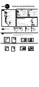
Step 1 Identify parts
Additional installation tools
Phillips Head Screw Driver
Pencil
Electric Drill
Drill Bits: 1/8'' drill bit for drywall
5/16'' masonry bit for cement wall applications
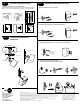
Step 3 Installation of the wall plate
Mounting to drywall.
1. Use the wall plate as a template and mark the screw hole locations onto the surface using a pencil.
2. Drill into the drywall with a 1/4'' drill bit. Insert the anchors into the hole as shown in fig. 3.
3. Secure with the #12 x 1-3/4'' screws, see fig. 4.
Mounting to solid concrete or cinder block.
1. Drill into the surface with a 3/16'' masonry drill bit 1-3/4" deep and insert the anchors into the holes as shown in Fig. 3
2. Secure wall plate with the #12 x 1-3/4" , see fig. 4.
1/8”
5/16'' mason bit
�
�
These fasteners and tools are provided
3 /3 2 ''
�
Step 2
Decide on location
�
Extension
Adjusting knuckle
Speaker plate
Mounting plate (1)
Screw covers
Mounting plate (2)
fig . 3
fig . 3
(1) (5) M4 X 12mm Phillips
pan head machine screw
(1) (5) M5 X 12mm Phillips pan
head machine screw
(2) (10) #12 X 3/4" Phillips pan
head self-tapping screw
(2) (10) #12 X 1-3/4'' Phillips pan
head self-tapping screw
(1) (5) 5/32'' Hex key
(2) (10) Plastic anchor
(1) (5) 8-32 X 5/8'' Phillips pan
head machine screw
(1) (5) Circular nut (PEM)
8-32 thread
(1) (5) 1/4-20 X 1" Phillips pan
head machine screw
(1) (2) 3/32'' Drill bit
fig . 4
fig . 4
�
�
�
AB2/AB2 HTS INSTALLATION INSTRUCTIONS
fig . 2
�
1 3 /4 "
fig . 2
�
1 3 /4 "
�
�
�
AB2 HTS AB2 HTS
K n u rle d sid e