POWER 40 Motorized Wall Mounting System ULN # PN # UL10333 POWER 40 = L3-UL10333-PRO-102908vE Maximum screen size: 40” Maximum weight 66 lbs - 30 KG CAUTION: DO NOT EXCEED MAXIMUM LISTED WEIGHT CAPACITY. SERIOUS INJURY OR PROPERTY DAMAGE MAY OCCUR! EN ES FR Adapters Included Images may differ from actual product El producto real puede variar respecto a la imagen mostrada. Le produit réel peut différer de l'illustration.
WARNING! – ENGLISH WARNING! SEVERE PERSONAL INJURY AND PROPERTY DAMAGE CAN RESULT FROM IMPROPER INSTALLATION OR ASSEMBLY. READ THE FOLLOWING WARNINGS BEFORE BEGINNING. If you do not understand the instructions or have any concerns or questions, please contact a qualified installer. North America residents can contact OmniMount customer service at 800.668.6848 or info@omnimount.com. Do not install or assemble if the product or hardware is damaged or missing.
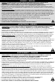
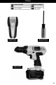
TOOLS EN Tools Needed ES Herramientas necesarias FR Outils requis Stud Finder EN Not included ES No se incluye FR Non inclus Screw Driver Power Drill P3
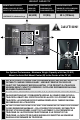
WEIGHT CAPACITY MAXIMUM WEIGHT CAPACITY MÁXIMA CAPACIDAD DE PESO CAPACITE DE CHARGE MAXIMALE POUNDS (LBS) LIBRAS (LB) LIVRES (LB) KILOGRAMS (KG) KILOGRAMOS (KG) KILOGRAMMERS (KG) MAXIMUM SCREEN SIZE TAMAÑO DE PANTALLA MÁXIMO TAILLE D’ÉCRAN MAXIMALE COMPLETE UNIT CENTER OF TV to Bottom of Logo 66 (LBS) 30 (KG) 40 in (1016mm) CAUTION! A B For Optimal Performance - Maximum Weight Capacity of 66 lbs (30 KG) Mount the Auto Wall Mount Center (B) to the Center of the TV (A) USE WITH PRODUCTS LARGER THAN
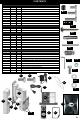
CONTENTS Monitor Kit – POWER 40 / MOTION 40 Description Pouch # Part # Qty M-A M-A 4 Philips Screws M4 x 12mm M-B M-B 4 Philips Screws M4 x 25mm M-C M-C 4 Philips Screws M4 x 40mm M-D M-D 4 Philips Screws M5 x 12mm M-E M-E 4 Philips Screws M5 x 25mm M-F M-F 4 Philips Screws M5 x 40mm M-G M-G 4 Philips Screws M6 x 12mm M-H M-H 4 Philips Screws M6 x 25mm M-I M-I 4 Philips Screws M6 x 40mm M-J M-J 8 Circular Spacers: 19.5mm OD x 8.25mm ID x 14.
STEP 1 5 1 2 EN Remove ES Retire FR Retirez EN Screw ES Tornillo FR Vis EN Disassemble ES Desmontaje FR Enlevez le pré montage P6
STEP 2 – VESA Patterns – OPTION 1 VESA Compliant • 100mm x 100mm • 200mm x 100 mm • 100mm x 200mm • 200mm x 200 mm • 200mm x 300 mm 200mm 100mm 100mm 300mm 200mm P7
STEP 2 – VESA Patterns – OPTION 2 VESA 400 mm Compliant • 200mm x 400mm 200 mm VESA Patterns – OPTION 3 VESA 400 mm 300 mm Compliant • 400mm x 400 mm • 300mm x 300 mm 300 mm 400 mm P8
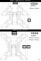
STEP 2 – VESA Patterns OPTION 2 – FRONT VIEW P-E 3 P-D X8 14 P-C X8 P-G X8 P-F X8 EN Attach EN Brackets ES Fijar ES Soporte FR Attacher FR Support OPTION 2 – BACK VIEW 400 mm x 200 mm P9
STEP 2 – VESA Patterns OPTION 3 – FRONT VIEW P-E 3 P-C X8 P-D X8 P-G X8 14 P-F X8 EN Attach EN Brackets ES Fijar ES Soporte FR Attacher FR Support OPTION 3 – BACK VIEW 400 mm x 400 mm 300 mm x 300 mm P10
CAUTION! – BOTTOM OUT & SPACERS EN Television ES Televisión FR Télévision **NOTE** WHEN INSTALLING FLAT PANEL TV DO NOT OVER TIGHTEN SCREWS AND MAKE SURE THAT SCREWS DO NOT BOTTOM OUT IN MOUNTING HOLES! EN Television ES Televisión FR Télévision M-J 3 CAUTION M-J EN Use spacers for recessed mounting holes or to access A/V inputs ES Use los espaciadores para agujeros de montaje empotrados o para acceder a las entradas de A/V FR Utilisez les entretoises sur les trous de montage encastrés ou pour accéder
STEP 3 3 M-A - M-I x4 EN Attach monitor using monitor hardware, M-A, M-B, etc… Coloque la pantalla utilizando los materiales de instalación de la ES pantalla, M-A, M-B, etc… Installer le moniteur avec les fixations de moniteur, M-A, M-B, FR etc… NOTE: If using BOLTS M-A (M4) – M-F (M5), then use WASHERS P-H P12
STEP 4 EN ES FR Top Superior Haut EN ES FR Television Televisión Télévision A=? EN Determine where you would like the TOP of the TV to be (Distance A = ?) Determine dónde desearía que esté ubicada la parte SUPERIOR del televisor (Distancia A = ?).
STEP 4 continued… TOP of TV Measure the distance from the top of the TV to EN the top of the wall plate (Distance B = ?) Mida la distancia existente entre la parte superior ES del televisor a la parte superior de la placa de pared (Distancia B = ?). B=? Mesurez la distance entre la partie supérieure de FR l’écran et celle de la plaque murale.
STEP 5 EN Find stud and mark edge and center locations. ES Ubique el panel y marque las ubicaciones de los bordes y el centro. Repérez l'emplacement d'une poutre, puis marquez l'emplacement des bords et du centre de FR cette poutre.
STEP 6 10 C=? EN Line the Top of Wall Plate Template (8), to the Top of Line C. Trace una línea desde la parte superior ES de la plantilla de la placa de pared (8) a la parte superior de la línea C. Enlignez la partie supérieure du gabarit FR de la plaque murale (8) avec le haut de la ligne C.
STEP 7 EN ES FR EN ES FR Drill pilot hole Realice el agujero piloto Percez le trou de guidage Wood Stud Wall Installation Instalación en pared con paneles de madera Installation murale sur poteau de cloison en bois EN Concrete Wall Installation ES Instalación en pared de hormigón FR Installation sur mur en béton W-A W-A x4 x2 1 1 W-B x4 Wood Pilot Masonry Pilot Pilot Hole Size Pilot Drill Depth Pilot Hole Size Pilot Drill Length 7/32" (5mm) 3” (70mm) 7/16" (12mm) 3 ½” (90mm) Included N
STEP 8 EN Level and install bottom wall bracket (wood stud mounting shown) ES Nivele e instale el soporte de pared inferior (instalación en paneles de madera como se muestra). FR Mettez à niveau le support mural du bas et installez le (voir illustration du montage des montants en bois). 2 W-A 2 1 1 2 EN Slide the mount into place and loosely install the top wall screw(s). ES Deslice el soporte hacia su lugar e instale, sin apretar demasiado, el/los tornillo/s de pared superior/es.
STEP 9 Good No Good 1 1 2 2 6 6 EN Level ES Nivel FR Niveau Use the provided level (P-B) and Leveling Adjustment screws (13) to ensure the mount is level before tightening the top wall EN screws (W-A). CAUTION: UNIT MUST BE LEVEL TO ENSURE MAXIMUM PERFORMANCE AND LIFE OF MOUNT. ES FR Utilice el nivel proporcionado (P-B) y los tornillos de Ajustes de nivelación (13) para asegurarse de que el soporte esté nivelado antes de ajustar los tornillos de pared superiores (W-A).
STEP 10 W-A 1 2 W-A 1 1 2 5 EN ES Install locking screw(s) Instale el/los tornillo/s de fijación.
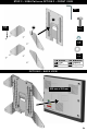
STEP 11 EN ES FR 1 4 Attach cover Coloque la cubierta Fixez le cache 2 3 1 4 2 EN Connect monitor and adapter to mount ES Conecte el monitor y el adaptador al soporte FR Connectez le moniteur et l'adaptateur sur le support P21
STEP 12 1 1 3 P-C x2 EN ES FR Install Monitor Locking screw(s) (P-A) Instale el/los tornillo/s de fijación del monitor (P-A) Installez la ou les vis de blocage de l’écran (P-A) P22
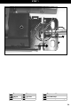
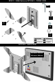
STEP 13 RS232 (only available on Some models) IR STEP 1: IR Receiver RS232 8 PWR STEP 2: Power 9 Connect Cables in order, IR (6) or RS232 EN (only available on Some models) and then Power Plug (7) Conecte los cables en orden, IR (6) o RS232 ES (sólo disponible en algunos modelos) y luego el enchufe (7) Branchez dans l’ordre suivant: d’abord le câble IR (6) ou le câble RS232 (fourni seulement FR avec certains modèles) puis ensuite la fiche d’alimentation (7) 8 9 8 EN Signal Receive ES Recepción d
Step 14 – Remote Control Programming (English) ATTENTION! EN Must set WALL DETECT RIGHT first. Failure to do this may result in poor performance of Wall Mount. If set LEFT WALL DETECT, please use the SETUP / RESET to clear memory.
Paso 14: Programación del control remoto (Español ) ES ATENCION! Primero, se debe establecer la DETECCIÓN DE PARED a la DERECHA. Cualquier falla que pusiera ocurrir al realizar esto, podría resultar en un escaso rendimiento del Soporte de pared. Si establece la DETECCIÓN DE PARED a la IZQUIERDA, utilice SETUP / RESET (INSTALAR / REINICIAR) para vaciar la memoria. PASO 1 = INSTALACIÓN Vacíe la memoria y establezca la posición cero. Empuje y apoye la parte plana del soporte contra la ES pared a 0 grados.
Étape 14 – Programmation de la télécommande (Français) FR FR FR ATTENTION! Vous devez d’abord régler la DÉTECTION DU MUR DROIT. Si vous n’y parvenez pas le support pourrait ne pas fonctionner normalement. Pour régler ensuite la DÉTECTION DU MUR GAUCHE, vous devez d’abord utiliser la fonction SETUP / RESET (RÉGLAGE / RÉINITIALISATION) pour remettre la mémoire à zéro. ÉTAPE 1 = RÉGLAGE Remet la mémoire et l’unité TV maison à zéro.
OMNIMOUNT PRODUCT WARRANTY ENGLISH This warranty applies to US Residents who purchase from an authorized OmniMount Dealer. OmniMount products are covered against defects in materials and workmanship for 1 year. OmniMount will repair or replace the defective component or product, at its sole discretion. To obtain warranty service, contact OmniMount customer service at 800.MOUNT.IT (800.668.6848) or info@omnimount.com. You must supply a copy of your original receipt.
(EN) English THANK YOU FOR PURCHASING AN OMNIMOUNT PRODUCT (ES) Spanish GRACIAS POR ADQUIRIR UN PRODUCTO DE OMNIMOUNT (FR) French MERCI D’AVOIR ACHETÉ UN PRODUIT OMNIMOUNT OmniMount Systems, Inc. 8201 South 48th Street Phoenix, AZ 85044-5355 1-800-MOUNT-IT (1-800-668-6848) www.omnimountpro.com All trademarks are the property of their respective companies. OmniMount is a registered trademark of OmniMount Systems, Inc.