
User's Manual

UM-003-A OPS243-A User Manual 13 OmniPreSense Corporation
UART Control – set to control the UART interface. The default configuration is 8-bits, no parity, 19,200
baud rate, and 1 stop bit. The OPS243 will start reporting out on the UART immediately after power on.
If the USB is enumerated, the UART reporting will be shut off and data will be reported out USB. It’s not
recommended to use OF with UART, especially at low baud rates.
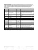
Command
Name
R/W
Value
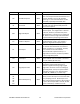
I?
Query Baud Rate
Read
Outputs current baud rate and oversampling
setting.
In
Baud Rate
Write
Set n to values 1, 2, 3, 4, or 5 based on desired
baud rate.
I1 = 9,600
I2 = 19,200 (default)
I3 = 57,600
I4 = 115,200
I5 = 230,400
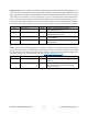
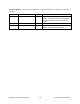
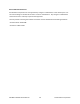
Simple Object Detection Interrupt – a simple output which trips if an object in motion or object in range
is detected. The signal is toggled on the interrupt pin. For the Doppler (-A, -C) radar sensors, the pin is
high when no motion is present and low when motion is detected. For the FMCW (-B, -C) radar sensors,
the pin is high when no object is in detected region and set low when and object is detected in the
detection region. For Doppler (-A, -C) radar sensors the interrupt can be filtered on speed (R>n, R<n),
signal magnitude (M>n, M<n), and direction (R+, R-, R|). For FMCW (-B, -C) radar sensors, the interrupt
can be filtered on range (r>n, r<n) and signal magnitude (m>n, m<n). Figure 7 shows how filtering can
allow detection for certain objects and mask out others.
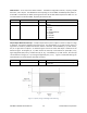
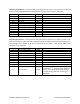
Command
Name
R/W
Value
IG
Object Detection Interrupt
Write
Turn object detection interrupt on. Use “Ig”
to turn off.
Figure 7. Speed, Range and Magnitude Filtering