
User Guide

OmniTek XR User Guide, Software Release 2.3 Page 59
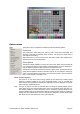
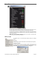
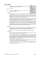
Options Menu
The Options menu allows you to adjust some specifics about
how the waveform traces are displayed.
In particular:
Data
For RGB type displays, the components can optionally be re-
ordered into the GBR order.
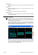
Graticule
The graticule lines can be displayed or hidden, along with graticule text labels. In
addition, amplitude markers may be overlaid onto the main graticules. These are
horizontal lines that can be used to mark out important levels. It is possible to define
multiple markers, and change which is displayed, or to display several at a time. It is also
possible to opt for minimal labelling on the various displays.
Note that the units for both axes of the graticules are customizable, using the global
selection on the File/Preferences menu selection. For example, this can switch between
decimal or hexadecimal values, or into a mV scale. See page 14 for details.
Lastly graticule calibration can be based around the standard SMPTE range of 64 to
940/960 (expressed as decimal, in 10 bit format), or alternatively around the full range of
0 to 1023 (again decimal, 10 bit). Full range video formats are particularly useful when
using RGB signals in a Dual Link set-up. For example, Thomson Viper cameras generate
RGB in the range 0 to 1023. Other cameras generate RGB in the range 0 to 940. Having
the variable calibration means the waveform monitor can be set to suit.
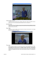
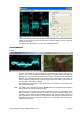
Crosshair
The visibility of the crosshair can be toggled. The crosshair appears as a cursor at a
given horizontal position on the waveform. If several components are displayed in the
waveform, then the cursor appears in the same place on each component.
The position of the cursor can be changed by clicking within the waveform window.
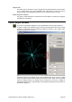
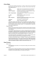
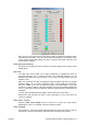
Look & Feel
The ‘Look and feel’ menu selection opens a dialogue that allows the colours of various
items to be customized (shown on the following page).
The colour of the graticule and of each supported waveform element can be individually
chosen. In addition ‘error colours’ can be specified uniquely for each different waveform
type for use when the waveforms breach the thresholds for valid video (specified in the
Engineering Settings control window, as described on page 22). It should however be
noted that the areas in error are not always clearly defined when the Interpolator is being
used to generate the display (see page 17).
The CRT emulation option applies a special filter to the waveform data to emulate the
look that is typical of analog CRT based waveform monitors.
The remaining options allow you to set the crosshair colour and the colour of the
measurement cursors, which can be used to measure time or amplitude between two
points as described on page 32.