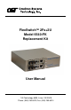
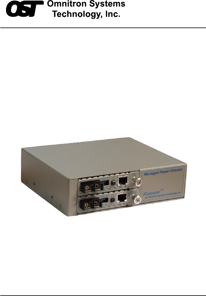
FlexSwitchTM 2Fx+2U Model 6540-FK Replacement Kit User Manual 140 Technology #500, Irvine, CA 92618 Phone: (949) 250-6510; Fax: (949) 250-6514
Table of Contents 1.0 1.1 1.2 2.0 2.1 2.2 2.3 2.4 3.0 3.1 3.2 3.3 3.3.1 3.3.2 4.0 4.1 5.0 6.0 INTRODUCTION .................................................................... 3 General Description ............................................................. 3 Chassis Models .................................................................... 3 INSTALLATION ...................................................................... 4 Chassis Installation ........................................................
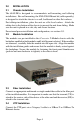
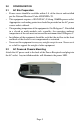
1.0 INTRODUCTION 1.1 General Description The 6540-FK is the direct replacement for the discontinued FlexSwitch Model 600XC 2Fx + 2U. The 6540-FK replacement kit consists of two iConverter 10/100Base-Tx to 100Base-Fx Media Converter Modules installed in a iConverter 2-Module chassis. The 6540-FK provides two 10/100 auto-negotiating UTP ports with auto-crossover and two 100Base-Fx fiber ports. The two 100Base-Fx fiber ports support half or full duplex operation.
2.0 INSTALLATION 2.1 Chassis Installation The 6540-FK is designed to accommodate wall-mounting and tabletop installations. For wall-mounting, the 8249-0 Wall-Mount kit (sold separately) is designed to attach the chassis to a wall, backboard or other flat surfaces. For tabletop installations, place the unit on a flat level surface. Attach the rubber feet to the bottom of the chassis to prevent the unit from sliding. Make sure the unit is placed in a safe, dry and secure location.
3.0 CONFIGURATION 3.1 AC Site Preparation • • • • • 3.2 Power source should be available within 5 ft. of the chassis and installed per the National Electrical Code ANSI/NFPA-70. This equipment requires a 100-240VAC, 0.5Amp, 50/60Hz power outlet. Appropriate overloading protection should be provided on the AC power source outlets utilized. The operating temperature of this equipment is 0 to 50 degrees C.
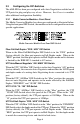
3.3 Configuring the DIP-Switches The 6540-FK has been pre-configured with Auto-Negotiation enabled on all UTP ports for plug and play easy of use. However, the iConverter modules offer additional configuration flexibility. 3.3.1 Media Converter Modules - Front Panel The Media Converter Modules have been pre-configured as illustrated below. Using the front panel DIP-Switch, the module can be re-configured for customer specific applications.
Note: Attaching the Auto-Negotiating UTP port of the 6540-FK to a device with a manual/forced /hard-coded UTP port may result in an unpredictable port setting with excessive collisions and poor link performance. When operating in Manual mode, both mating ports MUST be set manually to the same speed and duplex mode. 3.3.2 Media Converter Modules - On-Board The Media Converter Modules have on-board DIP-Switches for the configuration of the Link Modes and Backplane connectivity. See Section 6.
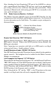
4.0 LED INDICATORS 4.1 Media Converter Modules The Media Converter Modules have LED indicators to provide information on how the module is communicating to its link partner. The LED indicators can also be used to troubleshoot problems with the connections.
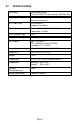
5.0 SPECIFICATIONS Description Fast Ethernet Switch with two 10/100 UTP Ports and two 100 Fiber Port Protocols 10Base-T, 100Base-Tx, 100Base-Fx with 1522 bytes max. frame size UTP Cable Type EIA/TIA 568A/B Category 5 and higher Fiber Cable Type Multimode: 50/125, 62.5/125, 100/140um Singlemode: 9/125um UTP Connector Type RJ45 Fiber Connector Type Dual Fiber: ST, SC DIP-Switches Fiber: FDX/HDX UTP: AN/MAN, 10/100, FDX/HDX Link Modes: LS, LP, RFD Power Requirements 100 - 240 VAC @ 0.5A/0.
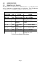
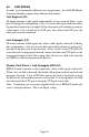
6.0 LINK MODES In order to accommodate different user requirements, the 6540-FK Media Converter Modules support three different link modes: Link Segment (LS) LS mode transmits a link signal independently of any received ‘Link’ at any port. Utilizing this configuration, a loss of a receive link signal will only affect the port detecting the loss of signal. All the other ports will continue to generate a link signal.
Warning The operating description in this Instruction Manual is for use by qualified personnel only. To avoid electrical shock, do not perform any servicing of this unit other than that contained in the operating instructions, unless you are qualified and certified to do so by Omnitron Systems Technology, Inc. Caution All user-required operations can be performed without opening the unit. Never attempt to open or remove the cover or tamper with the unit.
TECHNICAL SUPPORT If you encounter problems with this product, contact Omnitron Technical Support. Phone: Fax: Address: 800-675-8410 949-250-6510 949-250-6514 Omnitron Systems Technology, Inc. 140 Technology Dr., #500 Irvine, CA 92618 Email: URL: support@omnitron-systems.com http://www.omnitron-systems.