
User Manual


2.0 PORT STRUCTURE
2.1 OVERVIEW
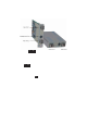
The front panel of the 2FXM provides access to the management (serial console) and fiber ports. The
fiber ports are SFP supporting 100BASE-FX transceivers. The plug-in module features two additional
Ethernet ports for connectivity via the chassis backplane.
2.1.1 Management Port
PI SA
The 2FXM features a Serial RS-232 Console Port (aka Craft Interface) which can be connected to a computer
for initial setup and configuration. The Serial Console Port is accessed through the mini DIN-6 female
DCE interface. Connect the interface to a computer’s DB-9 serial port using the mini DIN-6 male to DB-
9 female cable adapter (Part # 8082-0), which is included with the 2FXM.
An optional DB-9 male to female straight-through serial cable is available for extension (Part # 8081-3).
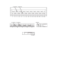
2.1.2 Fiber Ports
PI SA
The fiber interface supports the 100BASE-FX protocol. The fiber interface operates in manual mode and
supports half or full duplex operation. The fiber port can be enabled or disabled via network management.
A port disabled with the Port Access Control feature will still connect and allow 802.3ah OAM or IP-less
(secure) OAM communication, but blocks normal data traffic.
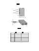
2.1.3 Backplane Ethernet Ports
PI
The plug-in module supports two additional 10/100Mbps Ethernet Backplane Ports. The Backplane Ports
A and B allow Ethernet data connectivity between adjacent modules in an iConverter chassis. The two
backplane ports can be disabled or enabled via a DIP-switch or network management.
The iConverter 19-Module, 5-Module, 2-Module and 1-Module Redundant Chassis backplanes provide
ethernet data connectivity between adjacent slots or ports. The A and B backplane ports connect the slots
as illustrated.
Page 4