
User Manual


3.2 CONFIGURING DIP-SWITCHES
PI SA
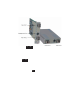
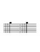
The 2FXM plug-in module has two board-mounted DIP-switches. The standalone unit has one bank of
DIP-switches. The locations of the DIP-switches are illustrated on below.
DIP-switch Locations
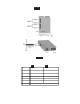
3.2.1 Board-Mounted Bank 1 Settings
PI SA
DIP-switch Bank 1 is available on both the plug-in and standalone modules. The table indicates the position
of the switch; Left/Down or Right/Up. As indicated in the DIP-switch location diagram, Left and Right
refers to the plug-in module and Down and Up refers to the standalone module.
PI
(Left/Right)
SA
(Up/Down)
Switch
Left/Down
(F actor y De fa ult )
Right/U p
SW1
Off:
Pause D i sable
On:
Pause Enable
SW2
FDX:
F ib er Po rt 1 Full-Duplex
HDX:
Fi ber Port 1 Half-D uplex
SW3
R eserved R eserved
SW4
R eserved R eserved
SW5
FDX:
F ib er Port 2 F ull-Duple x
HDX:
F ib er Port 2 Half-Dup le x
SW6 - SW8 See L ink Mo de D IP-Switch Ta ble in S ection 3.2.1.6
3.2.1.1 SW1 - Pause Disable/Enable “Off/On”
When the Pause Enable DIP-switch is “Off” position (factory default), the 2FXM disables the fiber ports’
ability to send and receive Pause frames during network congestion. Setting this DIP-switch to the“On”
position, enables the 2FXM to receive Pause frames from its link partner. This enables the 2FXM to stop
Page 6