
User Manual


transmitting traffic to its link partner and store incoming frames from the other port in the internal buffer
until the congestion clears. If the internal buffer of the 2FXM becomes congested, it will transmit a Pause
frame to its link partner.
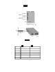
3.2.1.2 SW2 - Fiber Port 1 Full/Half-Duplex “FDX/HDX”
When the DIP-switch is in the Full Duplex “FDX” position (factory default), the fiber port will facilitate a
connection that supports Full-Duplex operation. Setting this DIP-switch to Half-Duplex “HDX” facilitates
a connection that supports only Half-Duplex.
3.2.1.3 SW3, SW4 - Reserved
These DIP-switches are for factory use only.
NOTE: DIP-switches marked Reserved must be kept in the LEFT (factory default) position.
3.2.1.5 SW5 - Fiber Port 2 Full/Half Duplex “FDX/HDX”
When the DIP-switch is in the Full Duplex “FDX” position (factory default), the fiber port will facilitate a
connection that supports Full-Duplex operation. Setting this DIP-switch to Half-Duplex “HDX” facilitates
a connection that supports only Half-Duplex.
3.2.1.6 SW6, SW7, SW8 - Link Modes
These three DIP-switches configure the link mode settings. The following table details possible Link Mode
DIP-switch configurations.
PI SA
SW6 SW7 SW8 Result
Left Left Left Enab les Link Se gment mode (LS ).
Right Left Left Enables Li nk P rop aga te mode (LP).
Left Right Left
Enables Remote Fault D ete ction mode plus
Link Se gment mod e (RF D+LS ).
Right Right Left
Enables Remote Fault D ete ction mode plus
Link Propaga tion mode (RF D +LP).
Left Left Right Enables Symmetrica l Fault Dete ct mod e ( SFD) .
Right Left Right Illeg al se tti ng. LS mode is enabled.
Left Right Right Illegal setting. LS mode is enabled.
Right Right R ight Illeg al setting. LS mode i s enabled.
SW6 SW7 SW8 Result
Down Down Down Ena bles Link Segment mode (LS ).
Up Down Down Ena bles Link P ropagate mode (LP).
Down Up Down
Ena bles Remote Fault Detec tion mode plus
Link Segment mode (RFD +LS).
Up Up Down
Ena bles Remote Fault Detec tion mode plus
Link Prop agation mode (RF D+LP).
Down Down Up E na bles Symmetrical F ault D e tect mode (S F D ).
Up Down Up Illegal setting. LS mode is e nabled.
Down Up Up Illegal setti ng. L S mode is enabled.
Up Up Up Illegal setting. LS mode is enabled.
NOTE: Connecting two converters set to any of the RFD modes are illegal and will cause a “deadly
embrace” lockup.
NOTE: It is recommended to keep the LS setting (default) until initial configuration is complete.
For detailed information on the operation of the different Link Modes, download the application note
“iConverter Link Modes” available on Omnitron’s web page:
http://www.omnitron-systems.com/downloads.php
Page 7