iConverter® 2FXM2 Media Converter and Network Interface Device STANDALONE AND PLUG-IN MODULE USER MANUAL Release 3.
Table of Contents 1.0 1.1 1.1.1 2.0 2.1 2.1.1 2.1.2 2.1.3 3.0 3.1 3.2 3.2.1 3.2.2 3.3 3.4 3.4.1 3.4.2 3.4.3 3.4.4 3.5 4.0 4.1 4.2 4.3 4.3.1 4.3.2 4.3.3 4.3.4 4.3.5 4.3.6 4.3.7 4.3.8 4.3.9 4.3.10 4.3.11 5.0 6.0 6.1 6.1.1 6.1.2 7.0 Overview .................................................................................................................... 3 General Description .................................................................................................... 3 Advanced Features ............
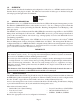
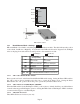
1.0 OVERVIEW This document describes the installation and configuration of the iConverter 2FXM2 standalone Network Interface Device and plug-in modules. The difference between the module types are indicated using the following legend throughout this User Manual: 1.1 SA - Standalone PI - Plug-In GENERAL DESCRIPTION The Omnitron iConverter® 2FXM2 Network Interface Device (NID) with integrated management provides Fast Ethernet (100BASE-FX) fiber-to-fiber media conversion.
2.0 PORT STRUCTURE 2.1 OVERVIEW The front panel of the 2FXM2 provides access to the management (serial console) and fiber ports. The SFP fiber ports support 100BASE-FX transceivers. The plug-in module features two additional Ethernet ports for connectivity via the chassis backplane. 2.1.1 Management Port PI SA The 2FXM2 features a Serial RS-232 Console Port (aka Craft Interface) which can be connected to a computer for initial setup and configuration.
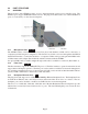
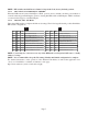
“A” Data bus “B” Data bus A A A A A A A A A A A A A A A A A A A B B B B B B B B B B B B B B B B B B B 1 2 3 4 5 6 7 8 9 10 11 12 13 14 15 16 17 18 19 19-Module Chassis “A” Data bus “B” Data bus B A A B 1 1 2 2 “A” Data bus B A A B 3 B A 5 4 3 B B Managed Power Chassis ™ iConverter by Omnitron Systems Technology, Inc. 5 4 5-Module Chassis B A A 2-Module Chassis A UTP Ports 1-Module Redundant Chassis 3.
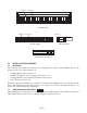
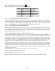
Switch 1 Bank 2 Switch 8 Switch 1 Bank 1 Switch 8 Left Right DIP-switch Locations 3.2.1 Board-Mounted Bank 1 Settings PI SA DIP-switch Bank 1 is available on both the plug-in and standalone modules. The table indicates the position of the switch; Left/Down or Right/Up. As indicated in the DIP-switch location diagram, Left and Right refers to the plug-in module and Down and Up refers to the standalone module.
NOTE: DIP-switches marked Reserved must be kept in the Left (factory default) position. 3.2.1.5 SW5 - Fiber Port 2 Full/Half Duplex “FDX/HDX” When the DIP-switch is in the Full Duplex “FDX” position (factory default), the fiber port facilitates a connection that supports Full-Duplex operation. Setting this DIP-switch to Half-Duplex “HDX” facilitates a connection that supports only Half-Duplex. 3.2.1.6 SW6, SW7, SW8 - Link Modes These three DIP-switches configure the link mode settings.
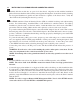
3.2.2 Board-Mounted Bank 2 Settings PI DIP-switch Bank 2 is only available on the plug-in module. Switch Left (Factory Default) SW1 A-DS: Backplane Port A Disabled B-DS: Backplane Port B Disabled Reserved SW2 SW3 SW4 M/SL: Master/Slave Auto-Select SW5 - SW8 Reserved 3.2.2.
3.3 INSTALLING PLUG-IN MODULES AND CONNECTING CABLES PI a. Carefully slide the module into an open slot in the chassis. Align the module with the installation guides and ensure that the module is firmly seated against the backplane. Secure the module by fastening the front panel thumbscrew (push in and turn clockwise to tighten) to the chassis front. Verify the “Pwr” LED is ON (indicating the chassis is powered). SA a.
3.4 CONFIGURE THE MODULE VIA COMMAND LINE INTERFACE PI SA To configure, attach the 2FXM2 to a DB-9 serial (RS-232) equipped computer with terminal emulation software such as HyperTerminal. The 2FXM2 Serial Console Port (DCE) is a mini DIN-6 female connector which can be changed to a DB-9 connector with the included adapter (Part #8082-0). Attach the ends of a serial cable to the serial port of the PC and the Serial Console Port of the 2FXM2. This is a standard asynchronous serial interface.
The Management Options screen will be displayed. PI SA Management Options iConverter, Serial Agent Network Management 1: Chassis and Module Management 2: Set Module Identifier Management Module Preferences 3: IP and Control Preferences 4: SNMP Preferences 5: Abandon Preference Changes 6: Save Preference Changes 7: Restore to Factory Defaults 8: Restart Management Module 9: Other Networking Features Management Module Maintenance 10: Firmware Update 11: Set Date/Time IP Address = 192.168.1.
3.4.1 Setting IP and Control Preferences An IP address is required for the SNMP manager to address the 2FXM2. The factory default setting is 192.168.1.220. The IP address can be configured manually or automatically as a DHCP client. 3.4.1.1 Setting IP Parameters Manually To manually configure the IP address and control parameters, select 3 from the Management Options screen. The IP and Control Preferences screen will appear.
PI SA Management Options iConverter, Serial Agent Network Management 1: Chassis and Module Management 2: Set Module Identifier Management Module Preferences 3: IP and Control Preferences 4: SNMP Preferences 5: Abandon Preference Changes 6: Save Preference Changes 7: Restore to Factory Defaults 8: Restart Management Module 9: Other Networking Features Management Module Maintenance 10: Firmware Update 11: Set Date/Time IP Address = 192.168.1.
PI SA IP and Control Preferences Screen iConverter, Serial Agent 1: 2: 3: Set IP Set Subnet Mask Set Gateway 192.168.1.220 255.255.255.0 192.168.1.
PI SA IP and Control Preferences Screen iConverter, Serial Agent 1: 2: 3: Set IP Set Subnet Mask Set Gateway 192.168.1.220 255.255.255.0 192.168.1.
PI SA SNMP Preferences Screen Chassis Number 1: sysContact 2: sysLocation 3: SNMP Writes iConverter, Serial Agent = 1 SNMP Engine ID 80001CAE03000687003B19 Omnitron (949) 250-6510 Irvine, CA USA Enabled SNMP 4: 5: 6: v1/v2c ------------------------------------------------------------------Read Community ***** Write Community ***** Agent Enabled SNMP 7: 8: 9: 10: 11: 12: V3 ----------------------------------------------------------------------Agent Enabled User 1 name (read only) guest User 2 name (
authNoPriv provides authentication based on the HMAC-MD5 algorithm and authPriv provides DES 56-bit encryption based on the HMAC-MD5 algorithm. To set User 1 security, select 10 at the SNMP Preferences screen, press and then follow the screen prompts. To set the User 2 security, select 13 at the SNMP Preferences screen, press and then follow the screen prompts. To set User 1 privacy password, select 11 at the SNMP Preferences screen, press and then follow the screen prompts.
3.4.3 Enabling/Disabling Soft-switch Reload The Soft-switch Reload function controls the configurations of the 2FXM2 and other iConverter modules managed by the 2FXM2 following a power up. When the Soft-switch Reload is disabled, the configurations of the 2FXM2 and the other managed modules (non-management modules) following a return of power are determined by their hardware DIP-switch settings.
3.4.4 Access the 2FXM2 Remotely Remote access to the 2FXM2 is provided via SNMP, Telnet, FTP or an external serial modem connected to the Serial Console Port. 3.4.4.1 Accessing the 2FXM2 via NetOutlook (SNMP) The 2FXM2 module can be remotely accessed by SNMP-client software such as Omnitron’s NetOutlook SNMP Management Software or third-party SNMP management software. See Setting SNMP Preferences Section 3.4.2, on how to configure the required parameters. NetOutlook Chassis View and Trap Log Screens 3.
PI SA IP and Control Preferences Screen iConverter, Serial Agent 1: 2: 3: Set IP Set Subnet Mask Set Gateway 192.168.1.220 255.255.255.0 192.168.1.
When the upload is complete, the 2FXM2 displays the update status and then automatically restarts with the newly loaded firmware. 3.4.4.4 Updating the 2FXM2 Firmware via FTP Using an FTP application, upload the new firmware into the FTP root directory of the 2FXM2. When the file transfer is complete, the 2FXM2 verifies the file and then automatically restarts with the newly loaded firmware.
4.0 DETAILED MODULE CONFIGURATION 4.1 OVERVIEW PI SA The 2FXM2 has module parameters that require configuration depending on the application. The Module configuration screen is accessible by selecting the module slot number from the Chassis View screen. To access the Module configuration menu, select 1 at the Management Options screen, press . The Chassis Selection screen will be displayed. From the Chassis Selection screen, select the chassis number where the 2FXM2 module is installed.
By selecting Chassis Number 1, from the Chassis Selection screen, the Chassis View screen will be displayed.
From the Chassis View menu, select the desired module (select 1 or 5), press . The Module configuration screen will be displayed.
4.2 MODULE MANAGEMENT MODE From the Module configuration screen, the management mode can be changed. Select option 18 to change the mode. The management mode options will be displayed.
4.3 PORT CONFIGURATION The Port configuration screen provides access to the port level configuration parameters, such as, Port Access, Bandwidth Control, L2CP Control, SFP information, 802.3ah, Port VLANs, Tagged VLANs and cNode Loopback. To access the Port configuration screen, select C from the Module configuration screen and press . The Port configuration screen will appear.
4.3.1 Port Access The Port Access option allows the ports to be disabled/enabled while maintaining the port configuration and network link To configure Port Access, select option 11 for the Port 1 and option 12 for the Port 2 from the Port configuration screen. 4.3.2 Bandwidth Control The 2FXM2 Bandwidth Control is accessed by selecting option 8 at the Port configuration screen. The 2FXM2 provides separate ingress and egress rate control on each port.
To change the ingress rate of the Port 1, select option 1. Change Fiber CIR (range 64 to 100000)> 142 To change the ingress rate of the Port 2, select option 6. Change Port 2 CIR (range 64 to 100000)> 100000 To change the egress rate, select option 4 for Port 1 or option 9 for the Port 2. The egress rates are displayed. Select the desired egress rate.
4.3.4 SFP Information The 2FXM2 module will provide general and specific information on the SFP. This information is best viewed with SNMP management software. The following is the information available: 4.3.4.1 SFP A0 Information Display This section displays fixed SFP Module information for the following areas.
SFP information can be obtained by selecting option 7 from the Port configuration screen. PI SA SFP Information - iConverter 2FXM2 Identifier Chassis Number = 1 Slot Number = 1 iConverter, Serial Agent Model Number = 8959N-0 Port = 1 Address A0 Page Contents =================================================== 00: 03 04 07 00 10 02 00 00 00 00 00 01 03 00 14 C8 ................ 10: 37 37 00 00 43 4F 52 45 54 45 4B 20 20 20 20 20 77..xxxxxxx 20: 20 20 20 20 00 00 00 00 43 54 2D 30 31 35 35 53 ....
• • • • OAM functions. 802.3ah OAM Mode - The 802.3ah OAM Mode sets the selected port to “Passive” or “Active” configuration mode. In “Passive” mode the port cannot initiate Discovery, send Variable Requests or initiate Loopback Mode. It can observe and report only the port status of its 802.3ah enabled remote partner. An “Active” port can initiate Discovery, send Variable Requests and initiate loopback mode. Loopback Mode - The Loopback Mode turns loopback operations “On” or “Off”.
ports. If “Forward” is displayed, the remote partner is forwarding non-OAMPDUs to the lower sublayer. If “Discard”, the remote partner is discarding non-OAMPDUs network frames. If “Unknown”, the Multiplexer state of the remote partner is indeterminate. • Parser Action - Indicates the Parser Action state (“Discard”, “Forward”, “Loopback” or “Unknown”) of the remote ports. If “Forward” is displayed, the remote partner is forwarding non-OAMPDUs network frames to the higher sublayer.
4.3.6 802.3ah Events 802.3ah events can be accessed by selecting options 6 from the Port configuration screen. PI SA 802.
4.3.7 Port VLAN The flow of data on the module is controlled by configuring the Port VLAN settings. The block diagram illustrates the flow of both the management traffic and the data traffic for a plug-in module (standalone modules do not have backplane access). The data traffic is controlled by a switch matrix which provides complete control of the data traffic. The management traffic is simply enabled or disabled at each port. By default traffic flows between all ports on the module.
Port VLAN is access by selecting options 13 - 22 or 13 - 15 depending on the module type; plug-in or standalone. PI Module - iConverter 2FXM2 Identifier Chassis Number Slot Number Model Number = 1 = 1 = 8959N-0 Feature Selection ---------------------------------1: 802.1Q Processing Enable Off 2: 3: 4: 5: 6: 7: 8: 9: 10: Configure Tag VLAN Control Configure VLAN Membership Save TAG VLAN parameters Configure 802.3ah parameters Configure 802.
4.3.8 Tagged VLAN The 2FXM2 supports the IEEE 802.1Q tag VLAN packet tagging and un-tagging and the 802.1p Quality of Service priority standards. The following parameters are configured for each port: 4.3.8.1 Port Priority (PRI) This (IEEE 802.1p based) user-specified value of 0 through 7 can be assigned as a QoS priority level (0 being lowest and 7 being highest) to packets ingressing (entering) a port. If no value is specified by the user, a default priority value of “0” is assigned.
Tagged VLAN is accessed by selecting option 2 from the Port configuration screen. The Tag VLAN Control screen will be displayed.
4.3.9 VLAN Membership Table The VLAN Membership Table lists the permitted VLAN ID (VID) for each egress port on the module. Only packets that are assigned a VID value that matches one of the egress port’s VID memberships are allowed to egress through the port. When the Ingress Security is set to High for a specific port, the membership table is used to list the VIDs of the packets that are allowed to ingress that port. VLAN Membership is accessed by selecting option 3 from the Port configuration screen.
Initially the table is empty. To configure the ports with VLAN IDs, select option (a) from the VLAN Membership configuration screen.
To add a VLAN ID to the membership table, select option 1 and enter the ID #. To associate the VLAN ID to a port, select the appropriate port option (2 - 6).
Once all the VLAN IDs have been assigned, select option 7 or 5 to save the entries. PI VLAN Membership - iConverter 2FXM2 Identifier Chassis Number = 1 Slot Number = 1 VLAN ID (VID) 1: iConverter, Serial Agent 100 Model Number = 8959N-0 Port 1 Port 2 BP A BP B Mngmnt Yes No No No No Add new entry (a), Delete entry (d), Edit entry (e), Clear table (c) Enter Choice, Previous Screen(0), (H)elp, E(x)it > The VLAN membership entries are saved from the Port configuration screen, option 4. 4.3.
4.3.11 Port Statistics The 2FXM2 module provides port statistics on both Port 1 and Port 2. The Port Statistics can be viewed by selecting option P from the Module configuration screen.
5.0 2FXM2 SPECIFICATIONS Plug-in Module Description Standalone Tabletop Standalone Wall-Mount 100BASE-FX Fiber to 100BASE-FX Fiber Converter and Network Interface Device Protocols 100BASE-FX with 2048 bytes max. frame size Cable Types Fiber Multimode: 50/125, 62.5/125, 100/140 um, Single-mode: 9/125 um Serial RS-232, 22 to 24 AWG, 12 to 50 pF/ft. Connector Types Fiber SFP: LC Serial Mini DIN-6 female, mini DIN-6 male to DB-9 female adapter included Controls DIP-Switches and LEDs 802.
6.0 TROUBLESHOOTING GUIDE 6.1 OVERVIEW The 2FXM2 module has several LED indicators available to assist in the determination of problems. Refer to Section 3.5, Verify Operation, for LED definitions. 6.1.1 Power Issues Problem: The Power LED does not illuminate after installation is complete or no LED indicators are ON Possible Causes: A. For standalone modules, confirm that the power supply is connected to both the module and the AC or DC power source.
7.0 WARRANTY This product is warranted to the original purchaser against defects in material and workmanship for a period of TWO YEARS from the date of shipment. A LIFETIME warranty may be obtained by the original purchaser by REGISTERING this product with Omnitron within 90 days from the date of shipment. TO REGISTER, COMPLETE AND MAIL OR FAX THE ENCLOSED REGISTRATION FORM TO THE INDICATED ADDRESS. Or you may register your product on the Internet at http://www.omnitronsystems.com.