
- Omnitron Systems Technology, Inc. Media Converter and Network Interface Device User Manual

AA AAAAAAAAAA AAAAAAA
BBBBBBBBBBBBBBBBBBB
1
2
3
4
5
678910
11 12
13
14
15 16
17
18 19
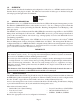
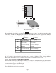
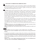
“A” Data bus “B” Data bus
19-Module Chassis
AB
12
3
4
5
AB ABAB AB
12
4
5
3
“A” Data bus “B” Data bus
AB
Managed Power Chassis
by Omnitron Systems Technology, Inc.
iConverter
™
“A” Data bus
AB
5-Module Chassis 2-Module Chassis
B
A
UTP Ports
1-Module Redundant Chassis
3.0 INSTALLATION PROCEDURE
3.1 OVERVIEW
The following steps outline the installation and configuration procedures for the 2FXM2. Refer to the
specified sections for detailed instructions.
• Configure DIP-switches (Section 3.2)
• Installing the Module and Connecting Cables (Section 3.3)
• Configure Module via Command Line Interface (Section 3.4)
• Verify Operation (Section 3.5)
When the setup and configuration procedures are completed, the 2FXM2 has been configured with the
basic setup requirement for standard operation. To configure the module with additional features, see
Section 4.0, “Detailed Module Configuration”.
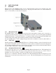
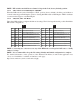
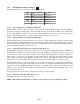
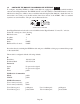
3.2 CONFIGURING DIP-SWITCHES
PI SA
The 2FXM2 plug-in module has two board-mounted banks of DIP-switches. The standalone unit has one
bank of DIP-switches. The location of the DIP-switches are illustrate below.
Page 5