
- Omnitron Systems Technology, Inc. Media Converter and Network Interface Device User Manual

Switch 1
Switch 8
Left
Switch 1
Switch 8
Bank 2
Bank 1
Right
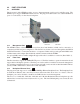
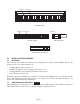
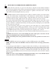
DIP-switch Locations
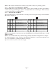
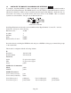
3.2.1 Board-Mounted Bank 1 Settings
PI SA
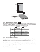
DIP-switch Bank 1 is available on both the plug-in and standalone modules. The table indicates the position
of the switch; Left/Down or Right/Up. As indicated in the DIP-switch location diagram, Left and Right
refers to the plug-in module and Down and Up refers to the standalone module.
PI
(Left/Right)
SA
(Up/Down)
Switch
Left/Down
(Factory Default)
Right/Up
SW1
Off:
Pause Disable
On:
Pause Enable
SW2
FDX:
Fiber Port 1 Full-Duplex
HDX:
Fiber Port 1 Half-Duplex
SW3
Reserved Reserved
SW4
Reserved Reserved
SW5
FDX:
Fiber Port 2 Full-Duplex
HDX:
Fiber Port 2 Half-Duplex
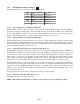
SW6 - SW8 See Link Mode DIP-Switch Table in Section 3.2.1.6
3.2.1.1 SW1 - Pause Disable/Enable “Off/On”
Pause operation is based on the Pause Disable/Enable DIP-switch setting. Setting the Pause DIP-switch to
the “Off” position (factory default) forces the port to operate in No Pause mode. Setting the Pause
DIP-switch to the “On” position allows the port to operate in Symmetrical Pause mode.
3.2.1.2 SW2 - Fiber Port 1 Full/Half-Duplex “FDX/HDX”
When the DIP-switch is in the Full Duplex “FDX” position (factory default), the fiber port will facilitate a
connection that supports Full-Duplex operation. Setting this DIP-switch to Half-Duplex “HDX” facilitates
a connection that supports only Half-Duplex.
3.2.1.3 SW3, SW4 - Reserved
These DIP-switches are for factory use only.
Page 6