
- Omnitron Systems Technology, Inc. Media Converter and Network Interface Device User Manual
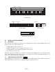

NOTE: DIP-switches marked Reserved must be kept in the Left (factory default) position.
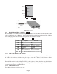
3.2.1.5 SW5 - Fiber Port 2 Full/Half Duplex “FDX/HDX”
When the DIP-switch is in the Full Duplex “FDX” position (factory default), the fiber port facilitates a
connection that supports Full-Duplex operation. Setting this DIP-switch to Half-Duplex “HDX” facilitates
a connection that supports only Half-Duplex.
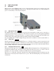
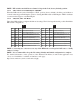
3.2.1.6 SW6, SW7, SW8 - Link Modes
These three DIP-switches configure the link mode settings. The following table details possible Link Mode
DIP-switch configurations.
PI SA
SW6 SW7 SW8 Result
Left Left Left Link Segment mode (LS)
Right Left Left Link Propagate mode (LP)
Left Right Left
Remote Fault Detection mode plus Link
Segment mode (RFD+LS)
Right Right Left
Remote Fault Detection mode plus Link
Propagation mode (RFD+LP)
Left Left Right Symmetrical Fault Detect mode (SFD)
RightLeftRightAsymmetrical LP P1 to P2 (ALP P1-P2)
Left Right Right Asymmetrical LP P2 to P1 (ALP P2-P1)
Right Right Right Asymmetrical RFD+LP P1 to P2
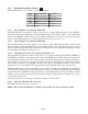
SW6 SW7 SW8 Result
Down Down Down Link Segment mode (LS)
Up Down Down Link Propagate mode (LP)
Down Up Down
Remote Fault Detection mode plus Link
Segment mode (RFD+LS)
Up Up Down
Remote Fault Detection mode plus Link
Propagation mode (RFD+LP)
Down Down Up Symmetrical Fault Detect mode (SFD)
Up Down Up Asymmetrical LP P1 to P2 (ALP P1-P2)
Down Up Up Asymmetrical LP P2 to P1 (ALP P2-P1)
Up Up Up Asymmetrical RFD+LP P1 to P2
NOTE: Connecting two converters set to any of the RFD modes are illegal and will cause a “deadly
embrace” lockup.
NOTE: It is recommended to keep the LS setting (default) until initial configuration is complete.
For detailed information on the operation of the different Link Modes, download the application note
“iConverter Link Modes” available on Omnitron’s web page:
http://www.omnitron-systems.com/downloads.php
Page 7