miConverter™ 18-Module Rack-Mount Power Chassis User Manual
Warning The operating description in this User Manual is for use by qualified personnel only. To avoid electrical shock, do not perform any servicing of this product other than that contained in the operating instructions, unless you are qualified and certified to do so by Omnitron Systems Technology, Inc. Caution All user-required operations can be performed without opening the chassis. Never attempt to open or remove the cover or tamper with the chassis.
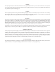
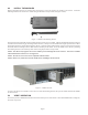
1.0 PRODUCT OVERVIEW The miConverter 1.5U (2.5 inch) 18-Module Power Chassis is powered by an AC or DC power supply and can accommodate up to eighteen miConverter media converters. This compact chassis is ideal for consolidating individual media converters into a high-density form factor utilizing a single reliable power supply. The chassis can be rack mounted in a 19” or 23” equipment rack. Figure 1: miConverter 18-Module Power Chassis 2.
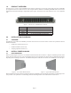
The chassis provides NEBS ground posts to secure a grounding lug and wire from the chassis to the ground post. Figure 4: NEBS Grounding Lugs When rack-mounting this equipment, the rack should be appropriately earth-grounded. 3.2 AC POWERED CHASSIS SITE PREPARATION Power source should be available within 5 ft. of the chassis and installed per the National Electrical Code, ANSI/NFPA-70. Model 1020-1 requires 100-240VAC, 0.4Amp, 50/60Hz.
WARNING REGARDING EARTHING GROUND: o This equipment shall be connected to the DC supply system earthing electrode conductor or to a bonding jumper from an earthing terminal bar or bus to which the DC supply system earthing electrode is connected.
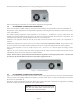
4.0 INSTALL THE MODULES Eighteen mounting brackets are provided with each chassis to secure the miConverter modules in the chassis. Attach the mounting bracket to the miConverter module using the flat head screw provided (see Figure 7 below). Figure 7: Module with Mounting Bracket The chassis provides guides/rails to assist with the insertion of a miConverter module. Align the module with the barrel connector towards the chassis and facing up (mounting bracket tab down).
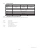
6.0 SPECIFICATIONS Chassis Type AC Powered Chassis 24VDC Powered Chassis Module Capacity Input Power Requirements (typical) 100 to 240VAC 50 to 60Hz 0.4A @ 120VAC Connector IEC320 Compliances +/- 18 to 36VDC 2.0A @ 24VDC +/- 36 to 60VDC 1.0A @ 48VDC 3-pin Terminal 3-pin Terminal UL, cUL, CE, FCC Class A Standard Operating: Wide Operating: Storage: Temperature Dimensions 0 to 50°C -40 to 60°C -40 to 80°C W: 17.5” x D: 9.5” x H: 2.5” Weight 7.20 lbs.